Proposal
With the wide availability of such commercial products as digital clocks, this report proposes a design for developing a digital clock through simple and accessible steps. There are many integrated circuits providing the functionality of modern digital clocks. The present report, however, suggests designing an integrated circuit based on the desired functionality of the device. The specifications of the proposed prototype include a simple display of 24-hour, 4 digits time. The report is divided into the following sections: an introduction with a brief historical background of digital clocks and a purpose statement, the design section outlining the main principles utilized in the prototype, the prototype section with simple explanatory schemes, and a conclusion.
Introduction
Digital clocks became an inseparable element of our everyday life. Although analog clocks are still used, although mainly for decorative purposes, it can be stated that when it comes to accuracy digital clocks are more widespread. The idea of digital clocks as commercial products can be traced to the 1950s, 1957 to be exact, when “[t]he Hamilton Watch Co of Lancaster, Pennsylvania, produced the world’s first electric watch” (BBC Guide). Since that time, the digital clock has gone through many refinements, although the main principle of its work remained the same. The principle is largely based on the functions of an ordinary analog clock, merely replacing mechanical components with electronics. In that regard, the functions in a digital clock consist of an electronic time base, having a regular signal repeated every single second, minute, and hour, a counter, and a digital display (Brain).
Despite the apparent simplicity, the process of building a digital clock can be far more complex, which nevertheless, does not reduce the experience of having a digital clock built on one’s own. In that regard, this report provides an overview of the process of building a 24-hour digital clock, indicating the different components used in the process.
Design
In this section the main components of the digital clock will be discussed in detail, outlining the general principle of their work. The design shall have the following features shown in table 1.
The overall scheme of the clock will look like outlined in Graph 1.
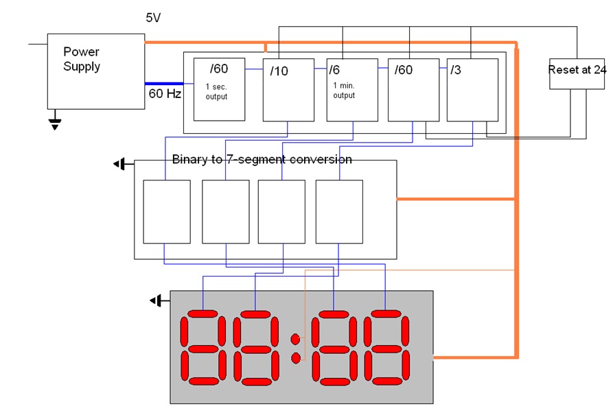
The general principle of the digital clock is can be explained through the division of the clock into 4 distinct parts, which are the power supply, counters, conversion and output. The power supply section will provide outputs, 5 V to power up the clock and the 60-Hz signal which will be used as a time base for the clock. The preservation of the 60 Hz sin will be implemented through the AC transformer, while the bridge rectifier will convert the AC voltage into DC. Accordingly, the output of the power supply section will result in a 60 Hz wave and a 5 V line. For the purposes of this report, it is implied that the 5 V line will be connected to every element of the clock, and accordingly, the same can be said about grounding.
The counter section of the digital clock will use several counters in order to convert the 60 Hz signals consequently into seconds, minutes and hours. As the built digital clock will not display seconds, such a section will be directly connected to the following counters without output on the display. The principle of the counters is the sequential division by 10 and by six, with the binary output representing sequentially the seconds, the minutes, and the hours (Brain). For the hour’s section, the division by 3 will make the maximal binary number on the ten-hour section equal two. The clock shall reset by connecting the output of the hour counters through a logical AND gate, which will reset the hour counters to zeros as 24 (Brain).
With the output of the counter section being in binary numbers, in order for them to be displayed as numerals, they have to be converted using, it is converted through binary-to-7 segments converters. The outputs of the converter are connected to each of the 7 segments of the LED. As stated earlier, only the minutes and hours sections are connected to the LED respectively.
Prototypes
Following the aforementioned outlined framework for the digital clock, the present report suggests a prototype that implements the parts outlined in the paper. The distinguishing feature of the prototypes can be seen in integrating the functions of the digital clock into a single circuit, with all the functions being built in. The functions include counters and binary to 7-segments convertors. The circuit is a modification of the scheme proposed on the website How Stuff Works, with the main parts numbers and characteristics being modified from there. The scheme of the IC can be seen in graph 2, where all of the outputs of this circuit should be connected to the LEDs.
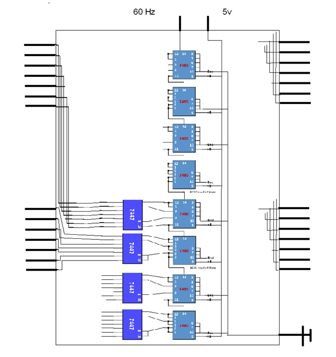
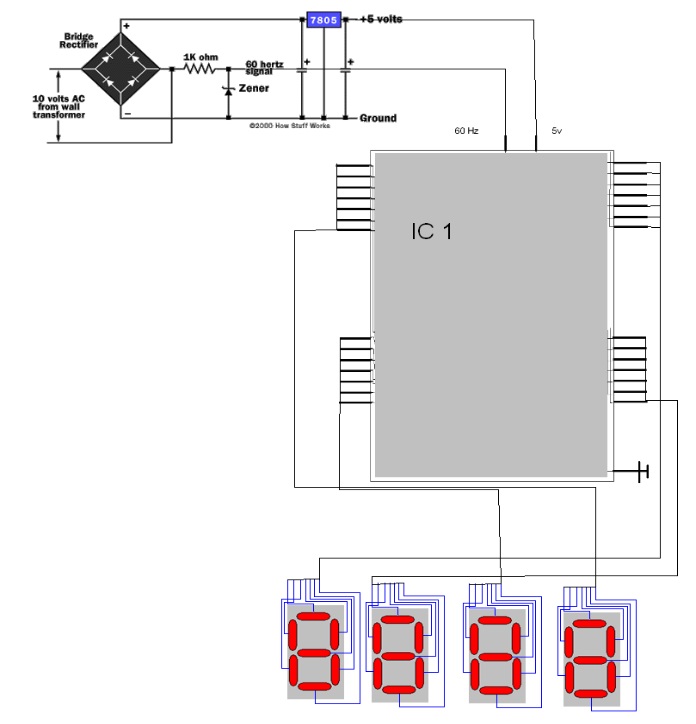
The aforementioned IC will serve as the core of the digital clock, where the power supply will serve as the input for it, with the output being the LEDs of the clock. It should be noted that only two convertors are connected in the scheme, due to limitations in the graphical output, whereas in real life all converters should be connected to the outputs of IC. In that regard, the complete scheme of the prototype can be seen through graph 3, where the IC is denoted as IC 1.
Other components of the circuit should include the set-up and the reset button, while at the same it can be modified further to work from other power sources, e.g. batteries. In the case of the latter, a crystal oscillator should be used. Accordingly, it should be noticed that the 60 Hz oscillation in this circuit implies the usage of a 110 V power line, rather than the 220 V used in many European countries. The enclosure of the clock shall have the dimensions indicated in the design section, although they might be changed in accordance to such parameters as the size of the used LEDs, wiring, and any personal preferences.
Conclusion
It can be concluded that the built project represents a simple implementation of the principles of clockwork in digital form. The proposed design is simple, yet, provides the essential functions of a digital clock, i.e. showing the time. Replacing the components with an integrated circuit can be useful in mass production. Unlike ready commercial products, the present clock can be modified to personal preferences, which include the size of the clock, the color of the LEDs, and others. Accordingly, new features can be added in the future such as an alarm, a calendar, and a different display.
Works Cited
Ashenden, Peter J. The Student’s Guide to Vhdl. 2nd ed. Amsterdam ; Boston: Morgan Kaufmann/Elsevier, 2008. Print.
BBC Guide. “The History of the Digital Watch”. 2003. Inventions. BBC. Web.
Brain, Marshall. “How Digital Clocks Work”. 2003. How Stuff Works. HowStuffWorks, Inc. Web.
“How to Make a Digital Clock”. 2010. EE Design Journal. Web.
MURTY, K. KRISHNA. “Standalone Digital Clock”. 2010. Kits’ n’ Spares. Web.