Introduction
The problem of creating an effective vacuum in many studies is important because different vacuum systems operate under different principles and can achieve the evacuation goal because of different evacuation abilities. Among the system to consider include the condensation systems, mechanical pumps, the ion and penning pumps that have different operating principles. On the other hand, during the evacuation process, it is possible to integrate a cryostat into the vacuum system because it provides a suitable environment to create a vacuum using existing pressure regions to achieve low cryogenic temperatures.
However, cryostats provide different evacuating capabilities because of they belong to different classes that include the continuous-flow cryostats, multistage cryostats, closed-cycle cryostats, and bath cryostats. The entire system can be set up using good light current and light sources and systems such as the exciton to study how vacuum systems can be created and used.
Vacuum System
The pressure reduction in a vacuum system is achieved by decreasing the gas pressure, the density, and volume of the gas in the system. Two techniques have been proposed as effective in reducing the density and volume of gas in an enclosure that leads to the reduction in the gas pressure to create a vacuum. The methods include ejecting the gas particles from the system into the atmosphere by use of different stages of gas particles compressions. The other technique involves removing the gas particles by condensing and making them to adhere to the surface of a body before being removed from the original container.
Some of the methods belong to the category that uses pressure reduction and the others belong to the category that relies on condensation of gas molecules to create a vacuum. One of the methods that are used to remove gas particles from a system to create a vacuum that was proposed by Benson (2008) uses a pulse or a mechanical pump.
Condensation system
The condensation systems are also known as ejector systems. Ejector systems rely on different ejector stages that consist of condensers arranged in series to reduce the pressure of the gas in the container to create a partial vacuum. The vacuum system works by allowing the fluid or gas to come into contact with the surface of the body as the fluid moves through a series of stages to the extent that the pressure and temperature permit.
Typically, the ejector has a fixed capacity that uses devices that are arranged in series and parallel to enable the system to control the pressure and other loads in the pressure reduction process. It is possible to use a single or a multistage non-condensing ejector to create the vacuum. In both cases, condensation is achieved at different levels of efficiency because the effectiveness of the system depends on the condensation stages that are used in each stage.
Many pumps have been designed and developed that belong to the category of high vacuum pumps and one of them is the diffusion pump. The diffusion pumps works by directing a jet of condensed of vapors at the air molecules to sweep them to the point where the fore pump forces them to the outside system. The only disadvantage with the system is that it cannot work at high pressures.
Mechanical Pump
Mechanical pumps work on the principle of removing gas molecules by reducing the pressure of a sealed container to create a partial vacuum. The mechanical vacuum pump works by use of a positive displacement of the gas molecules from a sealed container to deliver the gas molecules into the external system or the environment. Different pumps have different pumping capabilities that depend on the compression ratio of the pump (Wang & Hartnett, 2010).
The rotary vane pump is one of the many different types of mechanical pumps have been used to create vacuums. The rotary vane pump is driven by the use of an electric driven motor that has several sliding vanes that are used to create partial pressure as the vanes move. Typically, partial pressure is achieved by reducing the amount of gas molecules in a chamber without increasing the size of the chamber.
However, the system is not always perfect because of some leaks that occur at the points of contacts the pumping devices make with each other. In addition, leaks can occur or a reduction in pressure can occur if the pump has materials that can easily evaporate, that creates a virtual pressure that making effective leaks to occur in the system (Regier, Pieper & Matias, 2010).
Ion Pump
The ion pump was developed using plural cells that make it very efficient for gaseous evacuation. It has been shown that ionic pumps utilise highly efficient magnetic circuits that enables them to work efficiently in creating vacuums and when working under ideal conditions, the pump can reach a pressure of 10−11 mbar.
Penning trap
The penning pump works based on the penning effects where a penning trap is made to work by storing charged particles using homogeneous quadrupole electric and homogeneous axial magnetic fields that work effectively when used in precision instruments. A magnetic field is used to propagate the electrons under the strong magnetic field towards the anode. In the process of the movement of the ions towards the anode, the gaseous molecules and atoms in the chamber get ionized.
The ions that are generated from this process are accelerated towards the cathode because of the potential difference between the anode and the cathode and strike the cathode making it to be chemically active when the charges fall on them (Capatina, Islam, Trakhtenberg, Nojiri & Narumi, 2011). As the ions come into contact with cathode, they become embedded into the cathode or get embedded into the walls of the ion pump. The new ions pump the molecules through the chemisorption and physisorption processes (Chen et al., 2010).
Cryostat
Studies show that the cryostat can be used to create a confinement barrier to reduce thermal heat transfers from warm to less warm components to maintain low cryogenic temperatures. The engineering design of the cryostat is based on the minimization of the cost function to ensure that the best results are achieved when using the component (Chen, Bai, Bird, Bole, Cantrell, Toth & Zhai, 2010).
It is important when using the cryostat to ensure that the external pressure of the cryostat is made to be lower than internal pressure of the cryostat. That enables the cryostat to force the gas to flow from the high pressure region into the low pressure region. In practice, the gas cannot flow into the cryostat but will always flow away from the cryostat because of the pressure differences (Cosier & Glazer, 1986).
The dimension of the sample that is used in the experiment is the decision of the owner of the experiment. The diagram below shows the sample DCS that is 440 mm to achieve a “10% scatterer” that implies that of those neutrons that are released, about 10% of them are scattered and the setup can achieve multiple scattered, which implies that the particles can be scattered more than once when they have been released.
Pressure regions
On the other hand, when using the cryostat to pump the gas from the high to the low pressure region, it is important to pump until an adequate internal pressure is achieved. Once the “cryostat pump is removed, the internal pressure has to be made equivalent with the maximum number of molecules in the cryostat to ensure that the acceptable pressure prevails in the system” (Cosier & Glazer, 1986).
The structure consists of the penetration cover plates and system covers. In addition, the system consists of the neutral beam ducts, primary heat transfer systems, coolant penetration systems, thermal shields, gravity support systems, and vacuum pump penetrations.
Classifications
Cryostats are classified into continuous-flow cryostats, closed-cycle cryostats, bath cryostats, and multistage cryostats. The multistage cryostat is “used to achieve temperatures that are lower than those achieved with the use of helium gas” (Cosier & Glazer, 1986). By connecting the “He-4 isotope attached to the cold plate of the 1-K pot, it is possible to reach temperatures lower than of 1K” (Cosier & Glazer, 1986). A cold plate is used reduce the temperature of the system by using helium gas that is continuously replenished and that depends on the volume of the cryostat. To ensure that the temperature of the system is maintained as low as required, a vacuum shield is positioned around the system with a continuous replenishment of helium gas and helium vapor.
The continuous-flow cryostat uses liquid cryogens to keep the temperature of the system as low as possible. The system is designed to keep the temperature requirements by the use of steady replenishment of cryogen. The nature of cryostat makes them applicable in Magnetic Resonance Imaging (MRI) machines.
Pump
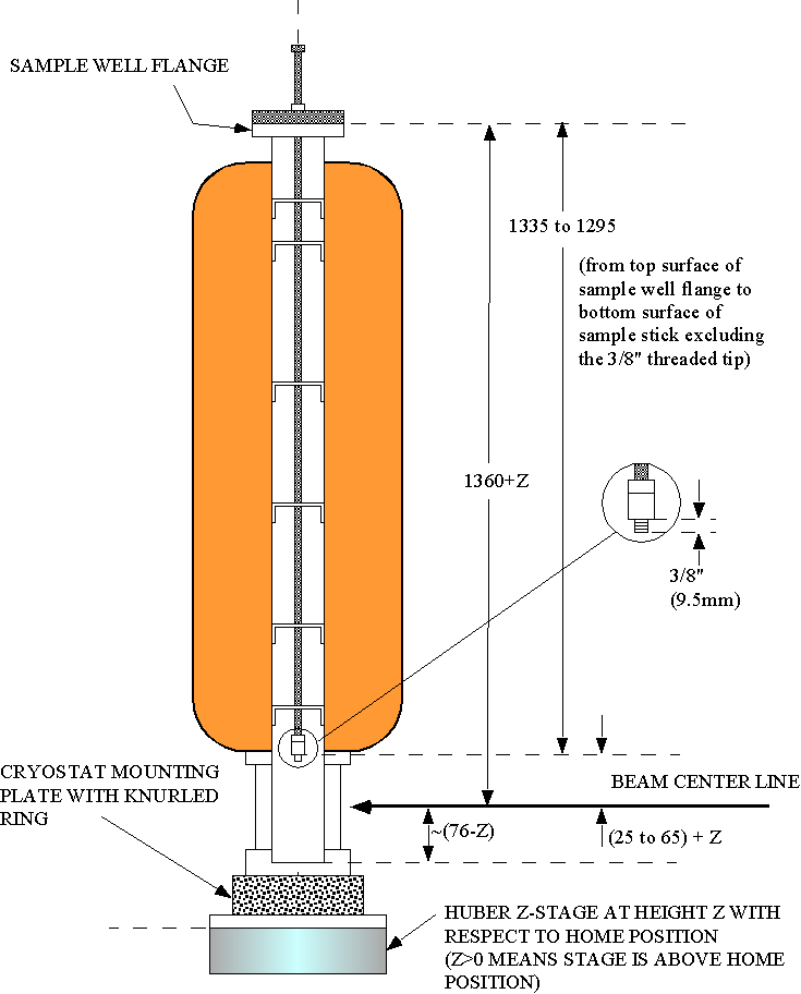
Different techniques have been applied to achieve the low temperatures desired for experimental purposes. When conducting an experiment using the cryostat to create an ultrahigh vacuum (UHV) pressure difference, the appropriate setup to use is shown below.
A sample chamber and a mixing chamber are setup as shown in the diagram below. The chambers are made of stainless steel and molecular turbo pumps that are used to create the required vacuum. Rotary pumps are used to create a vacuum so that the background pressure of 10−6 and 10−8 are achieved (Nataf & Ciuti, 2010). The mixing chamber for the samples and the high pressure bottles with pure gases are connected through the pressure reduction valves.
Both the closed cycle cryostat and the flow cryostat are used to cool the sample to the required temperature. In addition, thermal insulation is assured for each sample used in the experiment by use of insulating materials. The flow cryostat enables the samples to be moved using the x-y-z manipulator and the setup allows for movements to occur between the flow and closed cycle cryostats to be made possible (Chou, De Rouffignac, Stegmeier, & Vinegar, 1993).
To be able to control the continuous flow cryostat, liquid helium must be made available from helium Dewar, effective circulation of helium, a high vacuum pump to generate the required vacuum, and a temperature controller.
Types of pumps
Different types of pumps exist that can be used to pump and create the required vacuum. One of them includes the two stage rotary pumps that can use a cold trap to achieve a very low temperatures and pressures. However, the pressure achieved by use of the two stage rotary pumps cannot be used for such experiments. One of the most reliable pumps is the Cryopump. It is a single shot pump and it is very clean and appropriate for such experiments.
Temperature Controller
During the exchange of heat, a temperature controller is used to measure the temperature of the sample to ensure that the power supply is adequate for the experiment. The temperature is controlled by the use of the regulated heat injection techniques that uses a current carrying coil. Care is taken to ensure the thermal insulation of the system is adequately maintained because the system has been proved that it can hold the temperature to within a few millikelvins for several weeks. To achieve that efficiency the electronic temperature controls system must be designed and placed in a temperature controlled environment as shown below.
In practice, one can use the computer to interface between the system and the temperature controlling device. When setting up the system, one should ensure that the temperature controlling device is properly connected to the circuit as shown above (Isaksson, Kjäll, Nilsson, Robinson, Berggren & Richter-Dahlfors, 2007).
Light Source
Light is crucial in the experiment and collimated light enters through the spectrometer into the chamber where the study is taking place. The light source is also important because it enables the movement of the cryostat to be controlled effectively.
Light bulb
The light bulb is used to supply light to enable the movement of the particles to be recorded.
Power Supply
The source of power for use is the Micro regulator PID temperature control system that can be used to ensure that the temperature of the system is controlled to maintain it at the required level. The source of current is controlled by the use of a current amplifier and energy limiter circuits that is integrated into the system. An operational amplifier is used to increase the output current and has a configuration of the class AB push-pull and the circuit for the operational power supply and control sis shown below.
Monochromator
It is possible to use a high resolution trochoidal electron monochromator that can be housed in the UHV chambers and rotated freely while ensuring that the temperature of the system can be reduced to 15 K. Electrons from the monochromator gain sufficient energy to undergo the injection curve by entering into the multi-layered film on the substrate substance.
Chopper and Chopper Controller
The Chopper and Chopper Controller is used to provide the most appropriate source of light for the experiment based on an electric current chopper with a superconductor material. The niobium carbo-nitride is used to make the resistance component that is used to regulate the flow of current. On the other hand, “resistance means are achieved by the insulating plate and the resistance component is supported on the front side of the insulation plate and wherein a thermal mass is located within the cryostat against the reverse side of the insulating plate facing the resistance component to accelerate its cooling” (Medo, 1999).
Detector
It is possible to install the system with two detectors. However, the detectors can be used to measure the emissions that come from the sample that is used in the study. Studies show that the accuracy of the recommended DTGS detector for the study lies between 6,000 and 350 cm-1 or (1.7 to 28 µm). The diagram below shows how the detector can be optimized for use in the detection of the particles released in the experiment.
Limitation
The system is limited in the acquisition the particles that are used for the experiment.
Lock-in Amplifier
The amplifier can be used to collect signals that correspond to known wavelengths from the experimental environment that has a lot of noise. The noise level is increased by the presence and movement of different particles within the system that generates the particles under investigations (Nataf & Ciuti, 2010). In addition, the amplifier uses demodulation techniques to filter the incoming sine and cosine waves to remove noise and create a clean signal. The device measures any changes that occur in each signal phase, that are known as phase shift changes to recover signals that are hidden in the noise environment.
Function Generator + Amplifier (DC + AC)
The diagram below shows the setup of the function generator
Table of the specifications of the power supply for the experiment.
Exciton
The femtosecond vacuum pump is one of the typical examples where the exciton is applied. Experimental studies with pump–probe experiments require one to understand the behavior of excitons on different materials including semiconductors that depend on the coherence of excited electron states. Excitons are formed when semiconductors absorb photons because electrons are excited from the valence into the conduction band of a material (Nataf & Ciuti, 2010).
The concept of excitons that was established by Yakov Frenkel in 1931 classifies excitons into Surface excitons, Atomic, Wannier excitons, molecular, Frenkel excitons. For each category of the excitons, research studies show that long conjugated molecules have the ability to act as microwave conductors by use of conjugated molecules to enhance the conductivity of the molecules in organic semiconductors.
Exciton is a state that is achieved by the action of the electrostatic Coulomb force that binds electrons to each other in semiconductor materials, insulators, and in some liquids. It has been demonstrated that boosting the number of electrons and holes “increases the ‘pressure. However, excitons behave differently from metal conductors because it is possible to achieve elementary excitation states of condensed matter to allow for energy to be transported without any net effects on electric charges.
Semiconductor materials and exciton categories
There exists a structural difference between organic and inorganic molecules because organic molecules are bounded by van de Waal’s force that makes the material to have the unique electrical conduction properties. Results show that intermolecular forces between the molecules of the organic material commonly referred to as covalent bonds makes the dielectric constants usually low compared with the dielectric constant of inorganic materials as shown in the diagram below.
Frenkel excitons are usually based on strong and high Coulomb interactions between the hole and an electron leading to a low excitation state for materials with low dielectric constants. Studies show that excitation is possible within the molecules such as is evident with fullerene. Fullerene is a carbon molecule that exists in tube, sphere or ellipsoidal form. The binding energy of the Frenkel excitons in alkali crystals fall between 0.1 and 1 eV.
Another category of excitons is the Wannier-Mott excitons. The Wannier-Mott excitons occur when the electric field strength reduces because of the interaction between electrons and the semiconductor holes.
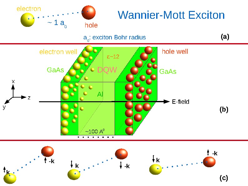
The results from the experiment show how different particles are bound within orbits of the atoms because “the particles energy is much lower than that of a hydrogen atom because of the screened coulomb effect and the lower masses of the particles as illustrated in the diagram below” (Nataf & Ciuti, 2010).
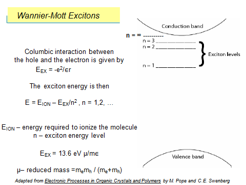
The above diagram shows the effects of the Columbic interactions and the effects that occur because of the interactions between the particles and the resulting changes. In addition, it shows the amount of energy that is required to cause excitations of the particles into other energy states. It is possible to have single wall excitations because of the way the holes and charges interact between themselves.
Interactions
It is important to understand how the interactions occur in semiconductor materials that allow for the emission of light at low temperatures. It has been shown that polariton are formed when interactions occur among the excitons (dressed excitons). Biexciton are formed when dressed excitons combine with other dressed excitons and as the density of the dressed excitons increases, electron holes are formed and that allows for the behavior observed with excitons to occur. It is also possible to achieve atomic and molecular excitons among molecules, ions, or atoms by enabling the particle to acquire a quantum of energy that excites and electron to move from one energy state to the other.
The state transition allows an electron to move into the electron hole from its lower energy state that exists in the highest occupied molecular orbit. However, such states are transitional and when the electron moves back into its normal state, it undergoes photon or phonon emission. The transient states and behavior of the molecules and electrons are important in energy transfer mechanisms that occur among different materials.
Conclusion
The study shows that vacuum pumps exist in different forms and have different pressure reduction abilities. Vacuum are created by the use of pressure reduction methods such as the condensation system that works by gaseous molecules through ejections, mechanical pumps that work through the creation of partial pressures, and the cryostat that works by ionizing gas molecules to create ions that pus the gas molecules from a high pressure to a low pressure region.
In addition, different pups are used to achieve the pressure reductions and to set up an experiment to study how to create vacuums, different elements have to be combined with different properties to create the desire environment. The elements include monochromator that uses a high resolution trochoidal electron, the Chopper and Chopper Controller that controls the flow of current, a detector, lock amplifier and other elements in the system. However, it is also important to conduct a detailed study in another area of special interest that uses excitons to create a vacuum.
References
Benson, W. (2008). U.S. Patent No. D575,792. Washington, DC: U.S. Patent and Trademark Office.
Capatina, D., Islam, Z., Trakhtenberg, E., Nojiri, H., & Narumi, Y. (2011). Mechanical design of a dual-cryostat instrument for a high-field pulsed magnet. Diamond Light Source Proceedings, 1(MEDSI-6), e42.
Chen, J., Bai, H., Bird, M. D., Bole, S., Cantrell, K., Toth, J., & Zhai, Y. (2010). Cryostat design for the HZB and NHMFL series-connected hybrids. Applied Superconductivity, IEEE Transactions on, 20(3), 644-647.
Chou, C. C., De Rouffignac, E. P., Stegmeier, G. L., & Vinegar, H. J. (1993). U.S. Patent No. 5,190,405. Washington, DC: U.S. Patent and Trademark Office.
Cosier, J. T., & Glazer, A. M. (1986). A nitrogen-gas-stream cryostat for general X-ray diffraction studies. Journal of applied crystallography, 19(2), 105-107.
Isaksson, J., Kjäll, P., Nilsson, D., Robinson, N., Berggren, M., & Richter-Dahlfors, A. (2007). Electronic control of Ca2+ signalling in neuronal cells using an organic electronic ion pump. Nature materials, 6(9), 673-679.
Medo, E. M. (1999). U.S. Patent No. 5,902,267. Washington, DC: U.S. Patent and Trademark Office.
Nataf, P., & Ciuti, C. (2010). Vacuum degeneracy of a circuit QED system in the ultrastrong coupling regime. Physical review letters, 104(2), 023601.
Regier, C., Pieper, J., & Matias, E. (2010). Dynamic modeling of a liquid helium cryostat at the Canadian Light Source. Cryogenics, 50(2), 118-125.
Wang, C., & Hartnett, J. G. (2010). A vibration free cryostat using pulse tube cryocooler. Cryogenics, 50(5), 336-341.