Introduction
A Linear Variable Differential Transducer (LVDT) is an electromechanical type of inductive transducer that converts rectilinear displacement into an AC electrical signal. Since LVDT is a secondary transducer, physical quantities such as force, weight, tension, and pressure are first converted into displacement by a primary transducer (Petchmaneelumka et al., 2020). LVDT is used to measure it in terms of the corresponding electrical signal (Bakshi et al., 2020).
Furthermore, because it is an AC-controlled device, there is no electronics component inside it (Kumar, George, and Mukhopadhyay, 2020). Its electrical output is obtained because of the difference in secondary voltages; hence, it is called a Differential Transformer. As such, it is the most widely used inductive sensor due to its high accuracy level.
Construction
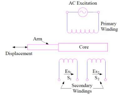
LVDT comprises a cylindrical former and three windings: one primary (P) and two secondary (S1 and S2). The secondary windings have equal turns and are placed symmetrically on either side of the primary winding. This arrangement ensures that the net output voltage is determined by the difference between the voltages of the two secondary windings. The diagram below shows the LVDT construction and its features (see Figure 1).
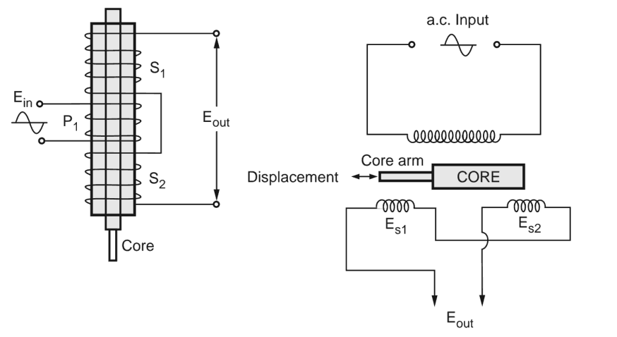
Hydrogen annealing improves the sensitivity of the Iron core and minimizes unwanted harmonics and residual voltage. The movable core is also laminated to decrease eddy current losses during measurement (Bakshi et al.,2020). The displacement to be measured is attached to the movable soft iron core. The LVDT is enclosed in a stainless steel housing to provide electrostatic and electromagnetic shielding.
Working Principle
The operating principle of the LVDT is based on mutual induction. When the primary winding of the LVDT is exposed to AC excitation of 5-15 Volts with a frequency of 50-400Hz, it generates a magnetic field (Gupta, 2019, p. 150). This magnetic field then induces a current in the secondary windings, resulting in two induced voltages, E1 and E2, in secondary windings S1 and S2, respectively. As the secondary windings are connected in series opposition, the net output voltage of the LVDT is determined by the difference between the induced voltages in the secondary windings (E1 and E2). The electrical equivalent circuit of the LVDT is shown below.
When the soft iron core is at the NULL position, the induced voltages in secondary windings S1 and S2 are equal (Es1 = Es2), resulting in a net output voltage (E0) of zero for the LVDT. This is called the NULL position, which is considered the normal position of the movable core with no output voltage (Teerdala et al., 2021). The core can be moved to the right or left of the NULL position. Therefore, by analyzing the two cases, it is possible to determine the movement of the core on either side.
Case 1: Core Is Moved Left to the NULL Position
If the core of the LVDT is shifted to the left of the NULL position, the flux linkage of secondary winding S1 increases relative to that of winding S2. As a result, the induced emf in winding S1 will be greater than in S2, meaning that Es1 > Es2. Thus, the net output voltage (E0) of the LVDT will be positive and equal to the difference between the induced voltages in the secondary windings (Es1 – Es2) (Garg et al., 2019). This implies that the output voltage (E0) will be in phase with the primary voltage.
Case 2: Core Is Moved Right to the NULL Position
If the core of the LVDT is shifted towards the right of the NULL position, the induced emf in secondary winding S2 will be greater than in S1. Thus, Es2 > Es1, and the net output voltage (E0) of the LVDT will be negative, equal to the difference between the induced voltages in the secondary windings (Es1 – Es2) (Garg et al., 2019). Consequently, the output voltage of the LVDT will be in phase opposition, 180 degrees out of phase with the primary voltage.
Advantages and Disadvantages
Advantages of LVDT
- LVDT produces a high output signal, eliminating the need for an amplifier circuit to magnify the signal.
- The LVDT core moves through a hollow former, so there is no friction loss, resulting in an accurate output.
- LVDTs directly convert linear displacement to an electrical voltage signal, which is easy to process further.
Disadvantages of LVDT
- Since LVDT is an inductive transducer, it is sensitive to stray magnetic fields, requiring an additional setup to protect it from such fields.
- As an electromagnetic device, it is susceptible to vibration and temperature changes.
Applications of LVDT in the Aviation Industry
- LVDT finds extensive applications in industries as well as in servomechanism systems.
- LVDT is widely employed in industrial automation, aircraft, turbines, satellites, and hydraulic systems.
- LVDT is ideal for measuring mechanical displacement ranging from a fraction of a millimeter to a few centimeters (Niku, 2020). It functions as a primary transducer, converting mechanical displacement into an electrical signal.
Conclusion
The LVDT is a widely used inductive transducer that converts linear motion into an electrical signal. It can transform mechanical movement into an electrical output proportionally. Additionally, the output voltage of the LVDT can indicate the direction of movement of the physical quantity. A positive output voltage means the physical quantity is moving to the left. In contrast, a negative output voltage indicates that the physical quantity moves from the NULL position to the right.
Reference List
Bakshi, U. A. et al. (2020) Electrical instrumentation & process control. 1st edn. Pune: Technical publications.
Garg, P. et al. (2019) ‘Noncontact dynamic displacement measurement of structures using a moving laser Doppler vibrometer’, Journal of Bridge Engineering, 24(9), p. 04019089. Web.
Gupta, S. V. (2019). Mass metrology: the newly defined kilogram. New York: Springer International Publishing
Kumar, A.A., George, B. and Mukhopadhyay, S.C. (2020) ‘Technologies and applications of angle sensors: a review’, IEEE Sensors Journal, 21(6), pp. 7195-7206. Web.
Niku, S. B. (2020) Introduction to robotics: analysis, control, applications. New Jersey: Wiley.
Petchmaneelumka, W. et al. (2020) ‘Linear-range extension for linear variable differential transformer using binomial series’, Sens. Mater, 32, pp. 475-485. Web.
Teerdala, R. et al. (2021) Instrumentation and control system. 1st edn. Chennai: Forschung Publications.