Abstract
Many people sit comfortably inside a car and enjoy this amazing technology without understanding the driving force behind the motion of a car. Moreover, others may have opened the hood of a car and wondered how this confusing jumble-like metallic structure called the engine, fitted with a mesh of wires and tubes executes its motion. In the face of all these dilemmas, the terminologies synonymous with the gurus of this awesome technology, for instance, the 3.0-liter V-6 engine leaves many others confused. Given all confusion, the literature in this paper will focus on the basic principle behind the engine, the pieces that constitute the entire staff, and finally, conclude on the research question- how we can improve the speed of a car with regards to piston modifications.
To increase the efficiency of a car’s engine, various elements require modifications. Among the elements that require alterations include the cylinder head and the rpm (revolutions per minute) of the crankshaft. As regards the modifications done on the cylinder head, terminology such as the ‘stroke,’ which is the diameter of the bore through which the piston travels, is widely used. This is the parameter that is adjusted.
On the other hand, when the focus is on the rpm of the crankshaft, such terminologies as the rod length and the torque are commonly used, and hence; require modifications. Importantly, since the rod and the crankshaft work in tandem and depend on the speed of the piston, a factor influenced by the stroke, it is important to optimize on all these factors to achieve maximum performance. The principle behind an engine motion
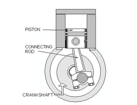
Whatever transpires in the inside of the engine to spark motion is energy transformation. Ideally, in the engine, the energy is transformed from chemical energy (gasoline/petrol chemical reaction) into mechanical energy via engine piston/crankshaft assembly. It is the motion of the pistons and the crankshaft that sparks the motion of a car. The common mechanism employed by the current engine designs is that they burn the fuel in-situ, eventuating in a motion. As such, these types of engines are christened internal combustion (IC) engines. Figure (1) below portrays the image of an IC engine, giving the details of its parts.
Before getting further, there are two things we need to note. First, there exist a variety of these types of IC engines based on the fuel used: these include the diesel engines and gasoline engines (Anyebe29); other variations of the IC engine e.g. rotary and HEMI engines exist, exhibiting their own merits and demerits. Second, as opposed to the internal combustion engine, there is also the so-called external combustion engine. To this end, an ancient technology, the steam engine, is an example of this type of engine. For this type of engine, fuel is burned externally to generate steam, which later sparks motion inside the engine. Of the two, the former is more efficient and significantly smaller than the latter (Horst 73).
Internal Combustion
The principle here is that the reciprocating combustion happening within an engine is continuously converted into mechanical motion. For instance, an air-gasoline mixture placed inside an enclosed container, called the cylinder (a, b), is ignited (c); a huge bang is heard releasing an awesome amount of energy due to the air-gasoline mixture expansion as gas.
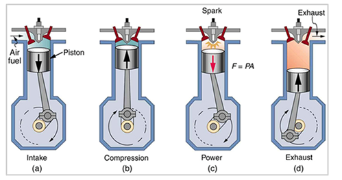
This gas expansion pushes against a moving piston connected to the crankshaft assembly, thus causing the rotation of the crankshaft. As the crankshaft rotates, the piston is pushed back into the cylinder. As the piston is pushed back, a valve opens to release gas trapped inside the cylinder cavity (d). Once the piston completes a complete cycle, another valve opens for the air-gasoline mixture to flow in.
The piston goes through another cycle of expansion, thus pulling more air-gasoline mixture into the cylinder cavity then compressing, thus compressing the air-gasoline mixture, before it is ignited again. This is known as a four-stroke combustion engine. Contemporary engines are typically four-stroke combustion engines. This engine, also known as the “Otto cycle” is the brainchild of Nikolaus Otto, an invention he made in 1867” (Horst 73). The details of the engine combustion chamber are exhibited in the picture below:
The mathematics behind the piston motion
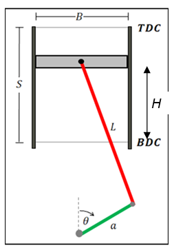
The linear motion of the piston within its housing or cylinder cavity is quite simple. Though simple, the motion within the cylinder requires high design precision and follows precise mathematics. Consider the cross-section illustration of a typical piston as shown below.
The table below shows the identities of all the unknown parameters shown in the figure above.
Table 1: shows the identities of all the unknown parameters on the figure.
To calculate the piston height (position), consider the figure below:
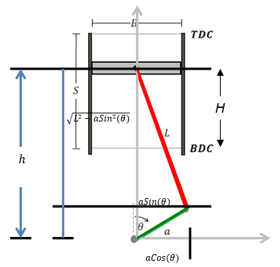
Given the crankshaft angle θ and the crankshaft radius (a), the additional components, aCos(θ) and aSin(θ), we can define piston height using Pythagoras theorem, as follows:
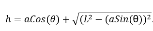
When the connecting rod is at the BDC position, i.e., the crankshaft radius points downwards, (θ=180°), h = L-a; and at TDC (θ = 0°), h = L+a. When the piston height is plotted vis-à-vis θ as per a revolution, the below wave is obtained.
A θ=0.2𝜫 , the piston is at TDC, therefore, h is maximum +a. The reverse is true when the piston is at BDC when θ=n (Gunston 67).
As anticipated, the piston height is highest when the crank angle equals 0 and 2 π (Setright 44).
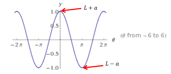
Also, the volume of the piston cavity (cylinder) can be calculated.The maximum volume coincides with the piston position at the BDC. As such, this volume is given by:

Instantaneous volume can be obtained as below:

Where; H represents the height of the piston about the BDC. When we substitute the term S with the derived terms above we obtain:

 A the plot of the volume versus the crank angle, as expected, reveals the pattern below with the maximum volume coinciding with the π (3.142).
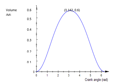
Similarly, the surface area of the piston is given by the sum of the inner areas of the cylinder head and that of the inner curved surface. Therefore, this is given by:
On substituting the values of S and H we obtain:
Consequently, with the above formula, one can evaluate how the piston height responds to the changing angular velocity of the crankshaft. This can then be plotted for analysis.
In this respect, if we assume that a car’s crankshaft with a= 0.5m and L= 1.5m was initially moving at a speed of 105 rads/s for one second, and then started to accelerate steadily to a speed of 210 rads/s within a second and remained constant, the below plot (figure 8) would be expected.
From the above information we derive the formula for finding the angular velocity as below: ω=Δθ Δt
Integrating the function between 1 and 2 seconds:

When θ =105 or 210 rads/s the angular positions are given as below:

Therefore, to find the trend of piston height (h) during the course of motion we apply equation (1) as below:
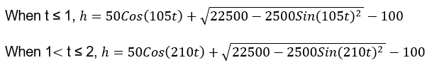
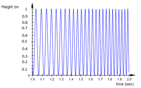
From the above equations you can find the different values for h between 1 and 2 seconds but in regards to their respective conditions to obtain the trend below.
Firing order
So far we have discussed the four-stroke cycles a single-piston goes through to turn a crankshaft. While a single piston can produce rotational power, it is not sufficient however for the practical locomotive. Further, from a mechanical point of view, a single-piston motor does not constitute an efficient or workable engine design. Accordingly, typical engines are produced with multiple pistons arranged in such a way as to work cooperatively to produce enough power as well as synchronized continuous motion. Typically, engines are designed with even number piston-arrangement, though there exist engines with an odd number of pistons.
As stated earlier, the internal combustion of the compressed fuel inside the cylinder is what derives the entire motion of a piston. So, for engines with multiple piston-arrangements, the internal combustion (sparkplug ignition) must occur in a synchronized fashion for the engine to produce practical and efficient motion. Now the question that lingers in the mind of many is how sparkplug synchronizes its sparking order concerning the appropriate position of each piston? The green light to spark or ignite the sparkplug is what is termed as the ‘firing order.’ Ideally, this firing order is synchronized in such a way that it is ignited when each piston is in the fuel compression stage.
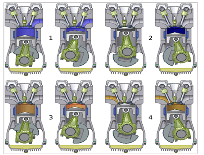
The sparkplug firing order is normally regulated by the distributor which sends currents accurately in pulses concerning the position of the piston during the entire cycle. The opening and closing of the valves that control the fuel flow inside the cylinder and exhaust are also synchronized and controlled by the mechanical assembly known as the camshaft. The piston movement also drives the camshafts and they are programmed to open and close the valves in a specific sequence to optimize the internal combustion and exhaust process as well as minimize undesirable effects e.g. uncontrolled vibration. For instance, in an in-line engine the plugs are named according to their positions concerning the engine from the anterior to the posterior in that order i.e. 1, 2, 3, and 4 (see figure 9 below).
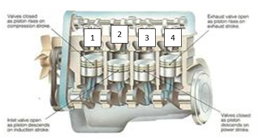
Engine optimum power output is produced normally when pistons are fired in sequence. So, during the compression stroke of each piston, a spark is emitted just before “the piston reaches top dead center (TDC) on the compression stroke” (Singal 38). However, assuming the compression stage in each piston is arranged to occur in sequence, i.e., 1, 2, 3, and then 4, the sparkplugs will also be arranged to fire in the same order. In such a case, the undesirable effect of enormous vibration would be felt thanks to the impulses emanating from the four pistons as they fire in one direction, i.e., 1, 2, 3, and then 4.
To decimate this effect, the compression stage and the sparkplug firing are arranged alternately e.g. 1, 3, 4, and 2. In this regard, mechanics ought to take caution when replacing the high-tension leads connecting the sparkplugs since a blunder in their placement may interfere with the correct sequence of the firing order, which may lead to undesirable effects. To further reduce undesirable effects of vibration and crankshaft hesitation, inertia generated from the rotating crankshaft-attached flywheel is used. Additional weights are further added to the crankshaft to enhance the engine’s stability.
How the valves open and close
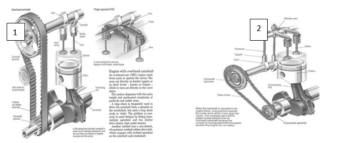
The valves attached to the combustion chamber of each cylinder of the engine are named literally as per their functions. As such, we have the inlet valve which acts as a vent through which fuel and air enter the engine, and an exhaust valve, which allows for the expulsion of exhaust fuel. They are synchronized to open precisely and periodically to enhance the smooth running of the engine. This opening and closing mechanism of the valves are controlled by a system that is composed of a pear-shaped lobe otherwise called cams that are mounted on a rotary shaft” (Setright 44). This assembly is referred to as a camshaft. The movement of the camshaft is controlled through a system of gears linking it to the crankshaft (see figure 10 below).
Where the camshaft “is mounted in the engine block, small metal cylinders tappets sit in channels above each cam, and from the tappets, metal pushrod extends up into the cylinder head” (Setright 45). The pushrods incorporate the rocker arm which constantly shuts the valve.
The mechanism of opening and closing is mechanical. First, the pushrod rises to rest on the cam, acting as a fulcrum for the rocker arm. In effect, the rocker arm pushes the valve held by a spring to open. As the camshaft makes a 360o turn, the spring overcomes the rocker arm to close the valve. This mechanism is dubbed the overhead-valve (OHV) system. Some designs don’t have pushrods thus they achieve this function courtesy of camshafts located in the head cylinder overhead-cam (OHC) system.
The basic engine parts/layout
The engine is the ‘heartbeat’ of the car, and it is the linear motion of the piston that eventuates in the motion of the car. The battery of reactions that results in this motion is executed by the sparkplug, which emits sparks, a source of heat that burns air-fuel mixture in-situ in what is dubbed internal combustion. To endure the massive workload, the engine ought to portray robustness in its structure. To this end, the engine is a composite of two basic structures: the massive lower structure housing the pistons (the cylinder block), and a lighter upper structure enclosing the head cylinder. The cylinder head is where the vents for air and fuel are located, and in isolated designs, this part also has vents designed to expel the exhaust fuel-air mixture.
The block is composed of the crankshaft, a structure that transforms the reciprocating “linear motion of the pistons into rotary motion of the crankshaft” (Horst, 1999). Moreover, the cylinder block encases the camshaft, a structure responsible for the periodic opening and shutting of the valves. The cylinders of the piston system “are cast into the block, as are mountings for ancillary equipment such as a filter for the oil which lubricates the engine, and a pump for the fuel” (Gunston 48). At the periphery of the crank casing at the bottom of the cylinder block is the slump, an oil reservoir (figure 11). The material choice for these basic parts depends on the density and the ease to dissipate heat. To this end, aluminum is the most preferred material since its light and has good conductivity.
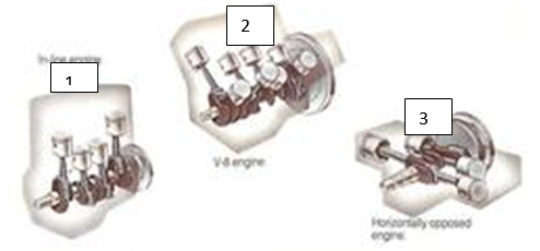
Having looked at the engine’s basic parts, it is important to understand the engine layout. Engine designs come in three different styles; the vertical layout, the V-shaped, and the horizontal shape. The vertical layout is the most popular design, with all the pistons aligned in a vertical position and the same direction (see figure 11 below (1). On the other hand, while the V-shaped design (2) limits the angle between successive cylinders to within reflex angles, a horizontal layout (3) has this angle permanently at 1800 (Vegburner 20).
How the piston of the engine of a car can be modified to improve a car’s speed
An engine’s efficiency can be modified on various fronts to optimize its performance. The areas that need optimization include among others the cylinder head, the general efficiency of the engine, and the rpm of the crankshaft. Of note, one common thing about these parameters is that they are based on geometric relationships. The rpm of the crankshaft is dependent on the piston’s speed, a factor vital in the determination of the overall speed of the car. This part forms the core of our discussion.
The piston’s speed is dependent on the cylinder geometry, which can be optimized by considering the stroke-to-bore ratio. Ideally, the size of the stroke is proportional to both the cubic inch displacement (CID) and the Torque (TQ). This can be explained by the equation below:
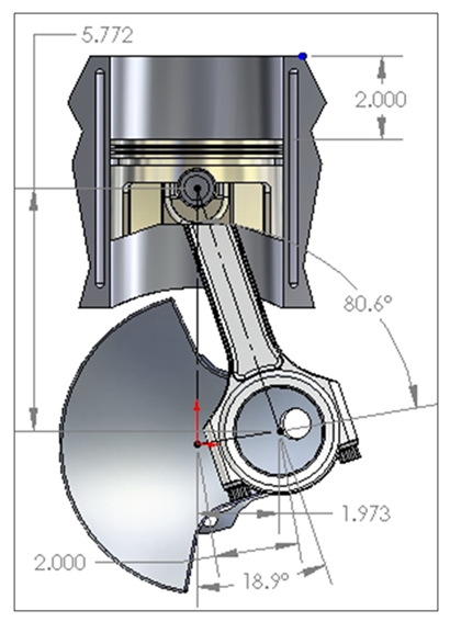
Assuming the term h to be the vertical height above the crankshaft, the velocity of the piston head (see figure 12 below) with regards to the crank angle (θ) can be obtained from the derivative of equation (1) – the piston height concerning the crankshaft angle.
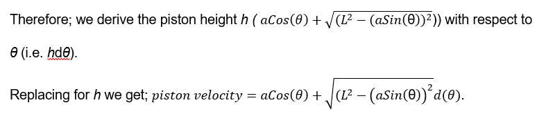
On simplifying the expression above we get:
 .
.
Equation (4) represents the piston velocity.
When we assume that we are working with a piston with the dimensions shown in the figure below (figure 12) we obtain the piston velocity as shown below:
Converting the units to SI units: 39,3701 inches
Therefore; a = 1.973in = 0.0501m
L = 6.1in = 0.1549m
 = 0.085 cm/s.
For this piston, the stroke-to-bore ratio is given by L/a is = 3.1
Now consider a piston with a stroke-to-bore ratio of 4. For this case, let’s assume that the rod length L is the same as the previous piston (0.1549m) and a is equivalent to 0.039m. The piston velocity will be given by:
 = 0.064 cm/s
From these results, it is evident that the piston velocity decreases with the increase in the stroke-to-bore ratio. In a synopsis, the efficiency of the engine can be improved by reducing this ratio. CID increases with an increase in piston length L. However, it should be noted that this modification on the flip side increases the friction, which decreases the engine’s horsepower (HP). To reduce friction, rings with low drag coupled with rods made up of lighter materials are applied. In addition, enhanced stroke decreases the rpm. Of note, enhanced torque coupled with minimum rpm translates to swift acceleration. The following examples demonstrate some of the extreme cases that have been experimented with and computed before:
The bore of 12.7 cm with a stroke of 6.1 cm translates to a torque of 421TQ/66.67 Hz, which is equivalent to 380HP/86.67 Hz rpm.
The bore of 10.2 cm with a stroke of 9.5 cm inch translates to a torque of 417TQ/61.67 Hz, which is equivalent to 368HP/83.3 Hz.
A bore of 7.6 cm with a stroke of 17.2 cm translates to a torque of 387TQ/66.67 Hz, which is equivalent to 313HP/78.3 Hz.
From the above analysis, it is evident that the engine’s CID is proportional to the torque. Nevertheless, this effect translates to a decrease in the engine’s horsepower. This happens irrespective of the stroke’s length or the cylinder radius. However, increasing “the bore diameter produces more torque; less horsepower loses to friction than stroking” (Gunston 67). As such, it is recommended to increase the diameter of the cylinder to enhance power, an effect that is enhanced further with more stroking.
Let us now check how the rod-stroke ratio affects the piston’s velocity. Velocity is a real-time rate of change in displacement. Concerning piston, this measurement always tries to establish how fast a piston “changes position concerning the reference point” (Gunston 67). Mathematically, this analysis is referred to as the first derivative concerning the position curve. For the sake of this analysis, the crank rotation is chosen as the reference point.
As it has been mentioned before, the main focus of this analysis is to check on the piston’s position concerning time, an effect that would influence the crank speed. Consider figure (13) below. The piston shifts from TDC to BDC, and therefore, the velocity moves from zero at TDC to an optimum then back to zero at BDC. The magnitude of the optimum velocity and its position vis-à-vis crank position is a function of the R/S ratio.
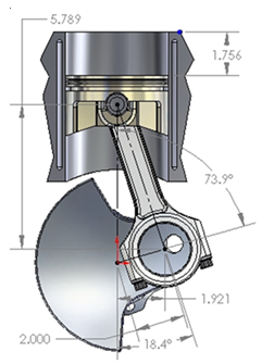
The figure above exhibits the piston’s position when at the optimum velocity before and after TDC. For this piston, the dimensions are given below:
Stroke = 4 in = 10.15 cm;
Rod length = 6.100 in = 15.24 cm.
As such, the rod-stoke ratio is given by:
15.25/10.15 =1.525
At this position, 73.9o from the TDC, the piston covers a distance given by:
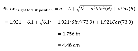
As such, it has completed only 43.9% (4.46/10.16 x 100%) of the entire stroke. With these parameters, and considering that the crankshaft moves at a frequency of 66.67 Hz, the optimum piston velocity obtained is 22.3 m/s (refer to formula 4). Nonetheless, for a longer stroke exhibiting the same rod to stroke ratio, the piston’s position at the peak velocity would be similar; however, the optimum velocity would be greater relative to the above. With this information, it is apparent that the rod-to-stroke ratio affects the eventual speed of the car. In this effect, to enhance the speed of the car, then one ought to maximize the ratio.
Another parameter of equal importance is the mean piston speed (MPS). This parameter is vital in the evaluation of engine efficiency. By definition, MPS is the average value of the piston velocity at a specific rpm. This is possible to establish since we know that the piston covers a distance that is approximately double that of the stroke per revolution. Consequently, the below expression is derived:
- MPS = RPM x 2 x stroke
As such, the MPS of an engine running at 4000 rpm and having a stroke length of 4 inches is given by:
- = 4000 x 2 x 4 inches per minute
- = 2667 feet/minute
- = 13.55 m/s
Given the equation above, it is apparent that the MPS is proportional to the stroke’s length. To this end, to improve the speed of a car to an optimum level then a designer ought to consider increasing this parameter to its peak. This influences the rate at which the crankshaft revolves.
Works Cited
Anyebe, Andrew. Combustion Engine and Operations, Denver: CO Press, 2009.
Audesirk, Thomas. Engine power, San Francisco, CA: Benjamin Cummings, 2008.
Doutor, Silva. The motion of a piston, Cambridge: Cambridge University Press, 2009.
Gunston, Brown. Development of Piston Aero Engines, Ambler, PA: Lippincott Williams& Wilkins, 2004.
Horst, Holweins. The Middle Ages of the Internal Combustion Engine, Society of Automotive Engineers 34.6 (2010).
Setright, Keith. “Some unusual engines.”Journal of mechanical engineers45.5 (2006).
Singal, Ranjay. Internal Combustion Engines, New Delhi: Kataria Press, 2004.
Singer, Joude. A History of Technology: The Internal Combustion Engine, Boston: Havard Engineering School Press, 1999.
Suzuki, Takuziki. “The Romance of Engines.”Society of Automatic Engineers 56.2 (2003).
Vegburner, Downing. Combustion Chamber Design, New York, NY: New York University Press, 2009.