Introduction
General idea
Erdal, 2003, states that this project seeks to provide fundamental information on the size of gas bubbles produced in oil from a cyclonic inlet to a gas/oil separator. FRAMES Separation BV support the work, and will consist of three phases:
- Phase 1 “Gas Carry under” – will measure the mean size of gas bubbles from the base of double cyclone over a range of gas and oil flow rates.
- Phase 2 “Liquid Turbulence” will measure the impact of gas carry under and the flow of liquid from the cyclone on the disturbance on the gas / oil surface
Scope of Work
All experimental work will be conducted using our existing U-separator (600m diameter, 2.2m long) supplied with oil from our existing storage tank. Fresh refined oil will be purchased from our usual suppliers and stored in a dedicated oil tank. For each experiment, the oil will be re-circulated through the separator allowing for several hrs of running per day. For the gas phase, air from the main compressed air supply, will be fed into the flow loop through our existing Tee section. For the majority of the experiments, our high-speed video camera will be used to provide sizing information.
Problem and solutions
Mathiravedu, 2010, states that severe problems such as pollution, loss of valuable data, and serious difficulties in the operation of a well test application have been known to be caused by foaming crude.
If foam is present during a well test or cleanup operation, the following problems may occur:
- Carry over in the gas line may cause pollution
- Good separation may be prevented, and separator capacity may be reduced
Foam increases the liquid level during well testing as a result of the foaming effect caused by the area filled by the bubbles, thus reducing the capacity of the separator. This causes gas entrained oil to travel down the oil line and through the liquid meters, due to lower retention time in the separator and reduced efficiency to separate foaming oil.
- Liquid and gas metering may be disrupted
- Cavitation
Pumping operations may be disrupted by foaming oil when pumping with centrifugal type pump.
Another place where cavitation can occur is at the separator oil dump valve, which can hunt as it tries to hold a constant liquid level in the separator.
- Burning problems may be experienced
Liquid droplets carried over from the gas line may fail to be atomized and burnt, causing pollution in the sea.
Foaming oil may be broken by a number of methods as follows:
- Good separator design
Wang, 2003, states that Foam may be broken down by applying that is not high enough to reduce the size to the entrained droplets. A proportion of the bulk liquid should also not turn into droplets by re-entrainment at the gas / liquid interface.
Maximizing the gas from liquid separation within the inlet device and ensuring that the contours of the inlet device are smooth, can keep foam generation in the vessel to a minimum.
Use of cyclonic inlet devices
Gomez, 2004, states that these are devices that are used to reduce the momentum of the incoming fluid stream. Separating the liquids and vapor into two discrete outlets or using a secondary device or as many other devices as is practicable inside the vessel, to evenly distribute the emissions from the outlets downstream can reduce the momentum of incoming fluid stream. Some separator vessels have up to four double banks of cyclones fitted in them, by Expro. The cyclone banks reduce momentum further and optimize the separation of gas / liquid and liquid / liquid. Well testing operations on known foaming crude applications have been carried out successfully by expro. Cyclonic inlet devices also reduce foam by ensuring pre separation of incoming bulk liquids.
High centrifugal forces created by the smooth surfaces of cyclonic inlet devices reduce the proportion of foam to total liquids by causing a considerable proportion of the foam to be broken down.
A controlled shear force is applied to the incoming liquids by the cyclones.
The main limitation of inlet cyclones is that they have to be correctly designed and controlled, otherwise gas or liquid may exit through the liquid or gas outlet respectively, due to different pressure drops across the cyclone outlets, thus reducing the effects of foam breaking.
- Settling
Ohnuki & Akimoto, 1996, state that as the oil passes through a separator, if its retention time is increased, the foam is given more time to break out of the oil.
A combination of this method and cyclonic inlet devices can virtually eliminate foam from the vessel.
Oil flow rates may limit this solution in some cases. Using two or more separators in series, while dropping the operating pressure of each separator at each stage, also referred to as stage separation, can be used to solve this problem.
Stage separation reduces foaming problems by allowing more gas to break out at each stage. Oil flow rates are only made at the final stage, where foam would not give false flow rates.
- Agitation
Agitation breaks foaming oil by reducing the time required for the gas bubbles to coalesce and separate from the oil. In well testing situations, it is not easy to achieve agitation.
- Application of heat
Heat applied through a heat exchanger break foaming oil by releasing the gas that is mechanically retained in the oil, thus reducing the viscosity and the surface tension of oil.
Heating, combined with agitation, effectively removes foam bubbles from foaming oil.
- Chemicals
Wang, 2000, states that Foam oil can be broken by any chemical which reduces the surface tension of crude oil. Silicon de – foamers, which destabilize the surface of foaming oil such that the foam bubbles lose balance, are currently considered as the most effective chemicals for breaking foam. Entrained gases are allowed to escape easily because the formation of the thin film which exists between pockets of gas is either not allowed, or the film is ruptured. The ideal point to inject such chemicals is the lowest possible point in the test string, such as the sub – sea tree.
The major drawback with this approach is that the effectiveness of these chemicals in the treatment of foaming problems differs, making it difficult to know which chemical would be effective for resolving a particular foaming problem.
The objectives of this project
- Focus on phase 1 this due to delay of cyclonic inlet to a gas / oil separator. And will use cyclone that designed by university.
- Determine bubbles size by analysis images that taken by high speed camera using Mat Lab code and Photoshop CS5 plus Microsoft word 2007.
Procedure
Flow rates:
This section will describe the steps to run 2 phase separator (U vessel) inside university Lab. After that, record the video by using high speed camera (9 sec time taken). This action will repeat for all runs below in different range of submerged length.
Operation system
Existing equipment used to include:
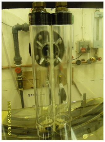
- U Shaped separator vessel, modified to hold the cyclone inlets. This will include a mechanism to capture the gas carry-over from the inlet to a separate tank.

- Double cyclone (inlet device)
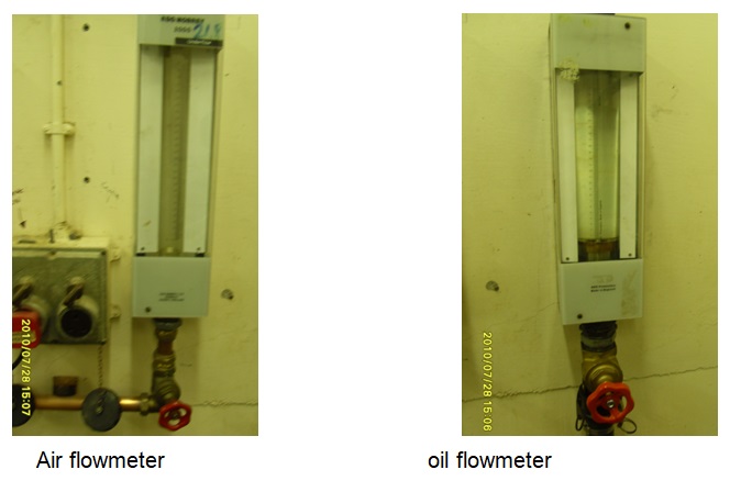
- Flow loop supply used to meter oil and air, as measured by two laboratory standard rota meters, to the U-shaped vessel. Existing pumps would be used to supply a maximum of 200 litres / minute
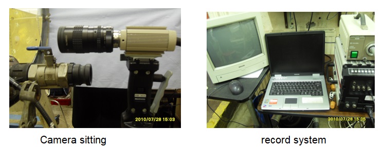
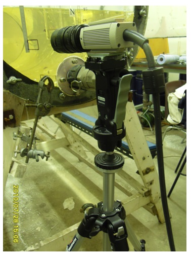
- High speed video camera to record images of the gas bubbles within the oil layer, gas bubbles on the gas / oil interface and waves on the gas / oil interface. This camera is a general resource and will be subject to a booking arrangement. Costs for a dedicated separate camera have been included below.
Connecting loop
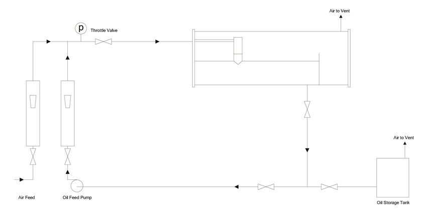
Sudden change in momentum is caused by Fluid entering the vessel and hitting the inlet diverter, which is where the fluid (that is liquid and vapor) is initially separated grossly. The force of gravity makes the liquid droplets to fall to the bottom of the vessel from the gas stream, and then leaves the separator through the fluid damp valve, which is regulated using a level controller.
The gas then leaving the vessel after flowing over the inlet diverter, through the gravity settling point, and then through the mist extractor. The mist extractor mostly uses plates to eliminate the very small droplets of the fluid in one last separation. This process usually takes place before the gas leaves the vessel.
In most cases, the force per unit area in the vessel is usually controlled by the use of a controller known as the pressure controller. The device tends to sense the changes in the pressure in the vessel and then sends signals. These signals control the rate at which gas leaves the vapor space of the separator, thus aiding the closing and opening of the pressure control valve.
One of the applications of the cyclone separator is the separation of the gas from the fluid in a multiphase measurement system. Multiphase meters are used in measuring the full stream flow with ought separation. However, these meters suffer much from the size and accuracy in a gas dominated flow most probably due to some errors. This problem can however be corrected by simply pre-separating most of the gas. Most of the multiphase metering applications are found to be gas dominated and falls outside the operational envelope especially for a typically full stream multiphase meter.
A two-phase separator is a vessel used to separate the well fluids into gases and liquid that is horizontal, vertical or spherical in shape the separators are either vertical or horizontal in which gases and liquids are separated by the means of gravity. In doing so, they settle with a mist eliminating devices. A case where they settle with ought a mist eliminating device exists. When one needs to measure the relative dimension, magnitude and the external appearance or form, bubbles and / or droplets, it is mostly recommended that you turn to the image-based analysis for size distribution measurement. Phase separators help one to fulfil all the needs to separate total liquid and gas from a production stream.
The separation mechanisms are as follows:
The gas-separation processes are mostly based on forces which include gravity, centrifugal and buoyant. The principles of mechanical separation in this case are classified as momentum, gravity, and filtration. On the other hand, when the phases are immiscible and have different masses per unit volumes, mechanical separation takes place.
The gas-separation processes by the different forces are as discussed below:
For mechanical separation by filtration, the process involved can be divided into three broad categories that includes, surface filtration and cake filtration among others. Filtration can be defined as the physical separation of a fluid-solid or a liquid-gas mixture where most of the fluid part (that is liquid and/or gas) passes through a porous material that retains most of the solid and or the liquid particulates that was present in the mixture. What come out is known as the filtrate (mostly fluid) while what remains on the porous barrier is known as the residue (mainly solid).
For mechanical separation through the forces of gravity, the fluid (mostly liquid) or solid particles tends to settle out of a gas phase if the force of gravity acting on the particle droplets is greater than the drag force that acts on the gas that is flowing around the particle droplets.
In the case of mechanical separation by momentum, what we need to note is that fluid phases will have different momentum if they have different densities. Greater momentum will cease to allow particles of a phase that is slightly heavy into turning around rapidly as the less heavy fluids. This only happens in situations when the phase stream changes their directions sharply resulting in greater separations.
Operation of a two phase separator:
It consists of a vessel, an inlet diverter, a skid breaker, a distribution baffle, a coalescing pack, a foam breaker, a vortex breaker, an oil sump and a weir, a mist eliminator, a sand jetting system.
The fluid jets in the system through the inlet nozzle from which it is divided into two distinct streams by the inlet diverter. Heavy fluids fall in solution and get settled at the bottom of the primary collection compartment. On the other hand, gases collect in the upper section of within the compartment.
The liquid that flowed through the inlet nozzle has a limited portion of the initial gas stream. This liquid influent flows up through a slotted distribution baffle. The slotted distribution baffle is where the equalization of the liquid flow takes place prior to the processing process through a point known as the coalescing pack.
As the fluid influent enters the coalescing pack, accumulation of particles like sands and slits get dislodged with the particles jetting system and are removed through the particle discharge nozzles. Customizing the coalescing pack helps to improve the coalescence of different phases resulting in an improved performance.
A skim layer is then formed at the surface of the water as a result of some of the rising particles. The skim layer is arraigned into different layers and therefore, as the fluid droplets flow to the water, the concentrated oil layer is as a result skimmed into the oil sump. The vortex breaker will then discharge the oil by the use of a pump. On the other hand, the free water fluid flows through a section in the device known as the free water section.The free water fluid is then discharged through a vortex breaker through the use of a pump or gravity.
Conventional fluid separators with ought the presence of a mist extractor to can be designed for gravity settling. This may be achieved through the use of the Stokes’s law equations. The separator may be incorporated in within a process scheme with different modes of operation. Its design shall be based upon the operation mode with the severest conditions. The severest conditions for fluids have the highest value of the embedded equation for the fluid separation that is in a knock-out drum where:
Q = Q (g) [rho (g)/rho (1) – rho (g)] ^ (0.5). The units for Q are in cubic meters per second, that is m^3/s.
From this point, it is very necessary to add on a given margin to yield the value after identifying the severest mode from the maximum value of Q. This helps in determining the value on which the separator design shall be based. However, the peak value of Q should be inclusive of the margins for over design, surging or safety.
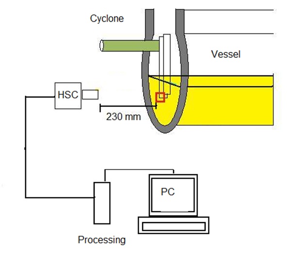
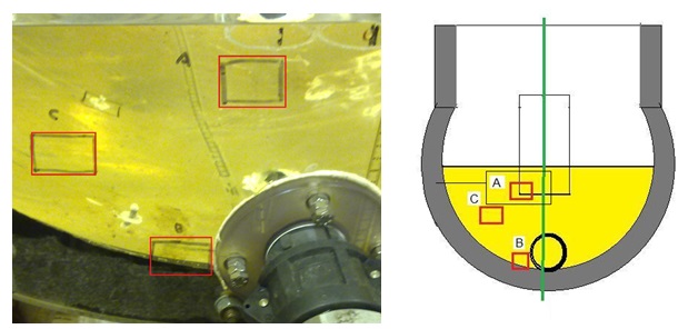
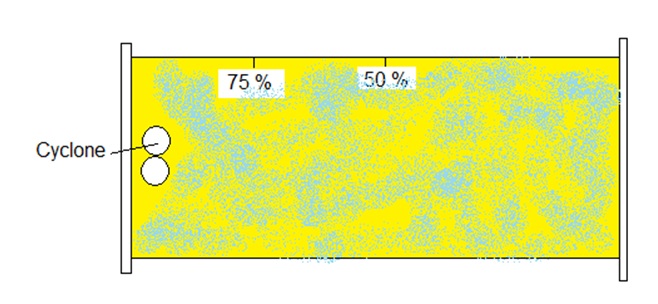
Camera position
The position to take videos and images is the wall of vessel, area C is better because Its presence in the middle of the front wall of the separator, as well as always most of the bubbles are going through in most operating conditions but sometimes you need to Move Forward away on a cyclone so that we can get the video with high quality.
- Area A: It’s very hard to get high quality video because it’s near to cyclone which is very turbulent area.
- Area B: also it’s not suitable to take videos that is due to bubble distribution in law flow rates.
In the Experimental study to measure Bubble size in two phase separator from a cyclonic inlet, we consider the experimental investigation of phase distributions of a two-phase air- to – silicon oil flow in a pipe (M. Abdulkadir and B. j. Azzopardi). The experiment is carried out by the use of an air/silicon oil mixture within a long riser. Superficial air velocities that are studied were ranging from 0.05 to 2.9 meters per second. A case where an optimum velocity of about 0.05 m/s is considered. The mean cross-sectional and time average radial void fraction measurements are obtained using a device known as the wire-mesh sensor (wms). The data are recorded at a certain acquisition frequency of about 100 hertz over an interval of one minute. For the following ranges of values and conditions, the average void fraction is observed to be varying between values of 0.1 – 0.9. Reasonable symmetry profiles are going to be observed when the air-silicon oil flows are fully developed. The shape of the symmetry profile is observed to be strongly dependent on the superficial gas velocity. The experiment is carried in the laboratory on an inclinable rig. The facilities comprised of the main testing section of the rig that is made from some transparent acrylic pipe that are made of glass.
Lighting system
There are two (back and front of vessel) different position of light by using three kinds of sources lighting
This figure show the position of three kinds of light sources.
The dimensions of the glass pipes should be about 0.067 m inside and about 6-7m of length so that one can easily observe the flow development over the testing point that is made up of shorter pipes that are easy to install and /or replace. The pipe is set up so as to be inclined from an angle of negative five degrees to an angle that is almost right angled. It is then mounted onto a steel frame. The steel frame could be positioned in the interval of about five degrees and it should be rigid. The positioning helps of the frames helps in investigating the influence of different inclinations on flow regimes.
WORKING: Compressed air is supplied from the main supply through valve (4) and it is measured by instruments called the air flow rot meters controlled by the valves (2) and (3). The rot meters used have a maximum range of flow rates of about 1001 per minute and 10001 per minute respectively. Another device known as the air distributor is installed right at the centre of the mixing chamber. The air distributor functions to make sure that all of the air coming into the pipe is well mixed and equally distributed through the cross section of the pipe is installed at the centre of the mixing section. Another valve is placed after the pressure gauge. This valve (labelled as valve five in the diagram) prevents the liquid from going through the air line to the rot meters when the valve is closed. Liquid fluid is stored in a liquid storage tank from where it is pumped using a centrifugal pump. Another valve is installed (valve 7) to help control the circulation of the liquid. The valve acts as a bypass valve. The flow rate coming through the testing section pipe is then measured by the use of some two parallel liquid rot meters that were initially installed. The flow of the liquid is controlled by the two valves (Valve 6 and valve 8). The inlet air-liquid mixture then enters the separator after coming out from the testing section pipe.
What happens in the separator?
While in the separator, air is drawn from the air-liquid mixture, and it is then released into the atmosphere from the top of the vertical two phase separator. On the other hand, the liquid get settled under the influence of the earth’s gravitational field making it flow through the bottom of the vertical separator and to return into the main liquid tank. The liquid is then drawn from the testing section tube by the use of a certain valve (valve 4), that is installed. The inclinable right is then converted into a riser that is vertical and it is used to examine the behavior of gas-liquid flows in a vertical riser by the use of a certain instrument known as the wire mesh sensor (WMS).The sensor has the ability to measure the existing difference in the electrical capacitance of both the two phases. It is built into an acrylic resin frame supports that makes it able to be mounted into the test pipe.
A distance of about five meters is okay for the positioning of the sensor away from the mixing section. The WMS also comprises of two planes that are made of twenty four stainless steel wires with 0.12 millimeter diameter. A distance of about 2.8 mm wire separation within each plane and an axial plane distance of about 2millimeter is considered in determining the spatial and temporal resolution of the sensor. However, only 440 of the total wire crossing points are found to be within the radius of the tube. This is because the square sensor is installed in a circular tube. When performing the experiment, one has to consider pulsing the transmitter lines one after the other. A capacitance signal (that is, a measure for the amount of fluid indicating the local phase composition in the grid cell) is determined from measuring the signal of all receiver wires that are vertical and crossing. In doing so, the local capacitance around the crossing points in the wire mesh sensor is known. Collect the data and take them to an acquisition frequency of about 1000 Hz over an interval of one minute. This way will help you determine the size of a gas bubble.
Quality of images
The Effect of light source position
- Lighting in front of vessel wall only
The picture is not clear enough because there are some spotlight of in the bubble and colures of bubble and fluid same this makes the analysis images difficult
- Lighting in front of and back of vessel wall
It’s very clear images and we can see all boundary of bubble
The effect of zoom camera
This part give us an idea that is which zoom factor is better to take video. During experimental work we find that zoom will be between 50 % and 70 %.
1: 70 zoom
Here there some bubbles not clear because the focusing field is very long that give us very bad video. As result, will find 3 or 4 bubbles comes behind
2: zoom 50
Now this image quite clear and we can see that bubbles very near to the vessel’s wall that can help us focus on all bubble one by one.
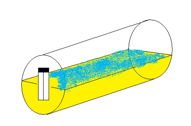
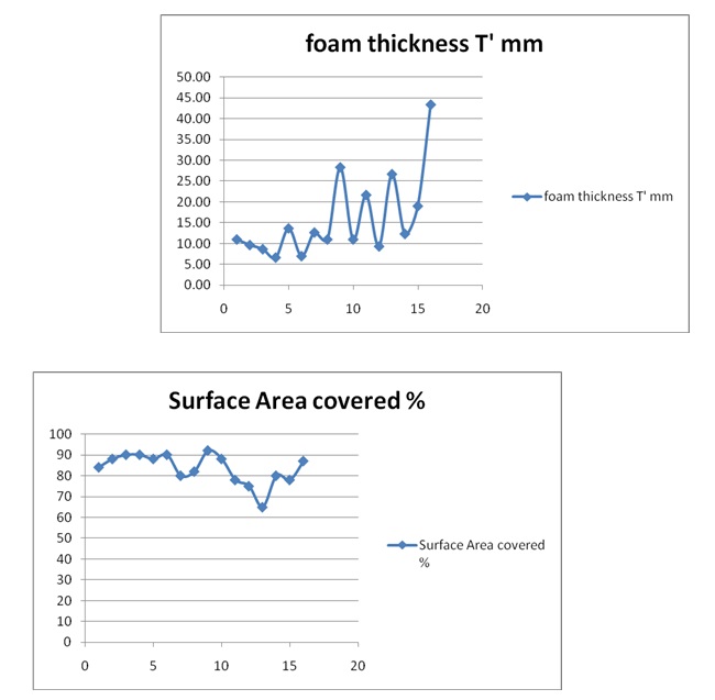
Foam thickness and cover
During run all flow rates I measure foam thickness which is that foam covered the surface area of fluid oil.
The method measurement
- Foam thickness T
Using ruler to measure in three different positions and take an average value
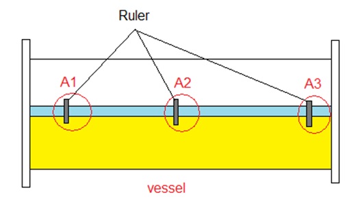
T’ = (T1+T2+T3)/3
- Foam cover
This part was measure by estimating optically (easy).
Measurement technique
Manual measurement technique
This technique I had use Photoshop CS5 and Microsoft word 2007.
Steps:
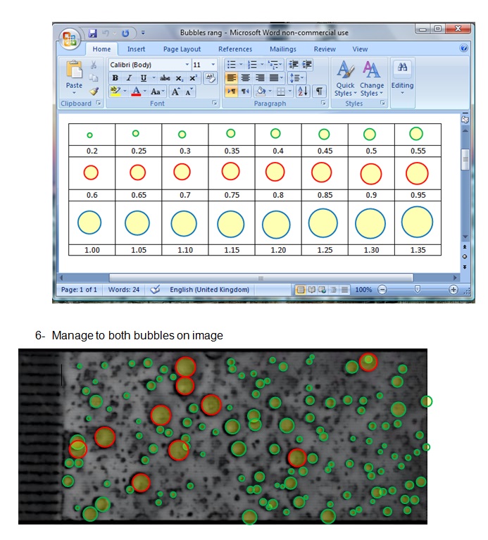
In This method we use Photoshop CS5 software to filtration frame firstly. Then, use Microsoft word 2007 to calculate average diameter of bubble.
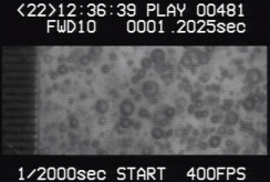
- Select best frame from 1 sec video this action by use image capture programme.
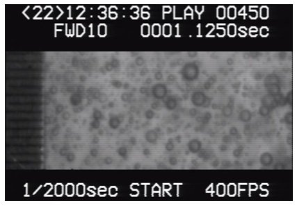
The criteria for selecting is take the images or frame that is contains different size of bubbles in the video. This step needs to see all video many times to make sure that image is best one in all videos.
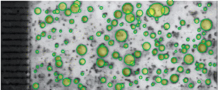
- Use Photoshop CS5 to filtration image
Press File + Open (image) + press Filter (filter Gallery)
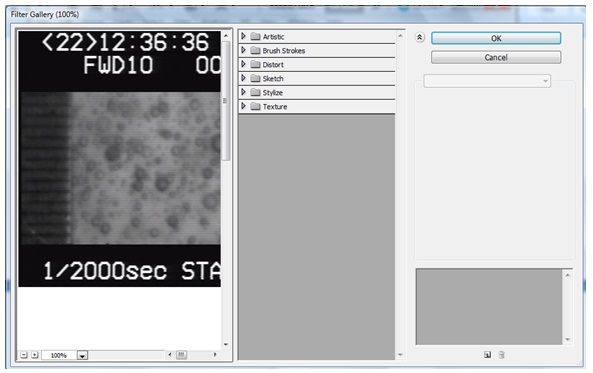
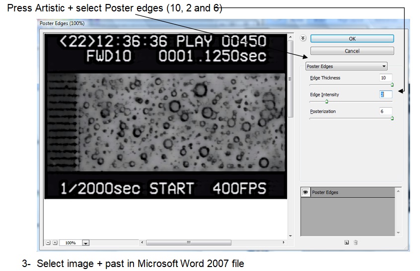
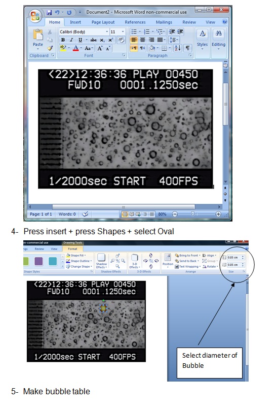
Repeat this step for all runs
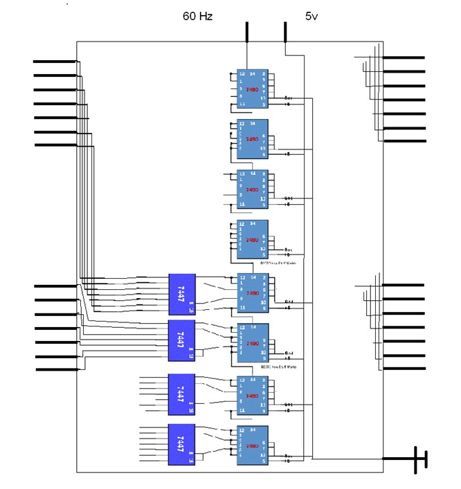
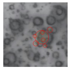
Mat Lab measurement technique
This is the progress so far on developing Mat lab code to analyse the droplet images from the High speed video camera, looking at gas bubbles in oil
This is a shot of the original frame, cut away from the whole screen to take out the boundary.
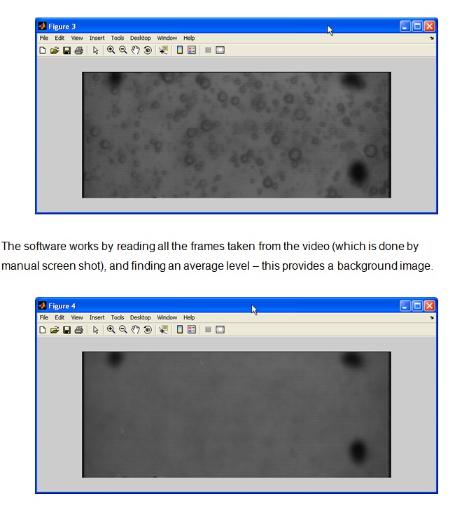
You can see here the three marker dots which are used for scaling.
Next the frame of interest is loaded, and the background subtracted. The image is normalised based on a maximum and minimum value. This gives a better contrast between the gray backdrop and the droplets.
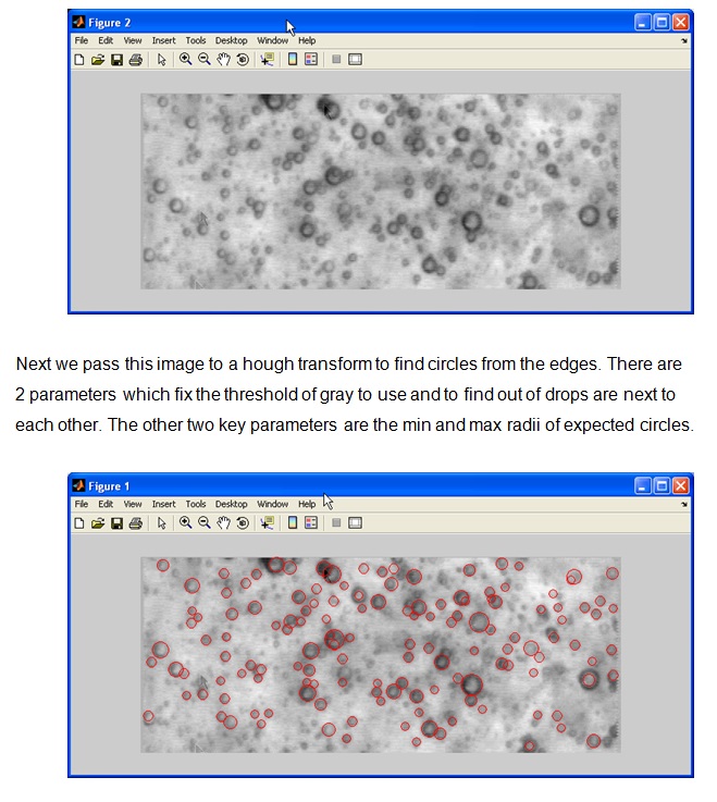
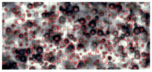
The hough transform gives the location and diameter of circles found in the image Note that not all the drops are detected, and some which we consider in the background are picked up. The problem comes from the larger droplets where the inner core is picked up and not the full outside.
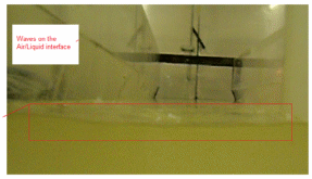
Liquid Turbulence
Disturbance of the air / oil interface due to liquid coming through the inlet is also of interest. Use the video camera (SONY HD 4.0 mega pixels) to record the amplitude of waves on the air / liquid interface for different feed rates. The challenge here will be to identify the location of the interface especially if foam is present. Analyze those videos could be give an idea about foam creation inside cyclone or on surface of oil layer due to turbulent flow.
Figure below show the Description of that method.
Flow rates that supply in this case:
Results & Discussion data
Results by manual method
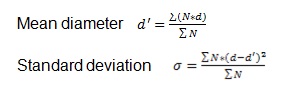
Bubble size result.
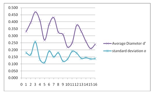
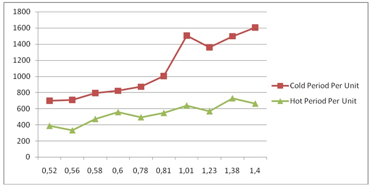
Figure: show d’ and σ for all runs.
Results by Mat Lab method
I’m still work on and I will send Mat Lab code too.
Final result of Foam thickness and cover.
Final result of Phase 2 “Liquid Turbulence”.
For a vertical two phase separator, the calculations are as follows.
The diameter: -The vessel diameter is represented by the symbol D (v) can be estimated from the embedded equation as shown below:
Q (peak)/ (pie/4 * Dv^2) ≤ 0.07
Where Q (peak) represents the process design value if Q plus margin.
The height
Consider the height if a vessel to hive the height is capable of the liquid hold-up, then the total height of the vessel will be given as:
H = h + d (n) + X + Y
Where the symbols have their meanings, that is:
D(n) represents the diameter of the nozzle, and it is measured in millimetres, X s approximated to be 0.3 D(v) with a minimum of 0.3 meters, and y 0.9 D with a minimum value of 0.9 meters.
Nozzles: -The nozzles involved in the vessel include the feed nozzle, the gas outlet nozzle, and the liquid outlet nozzle. The liquid outlet nozzle has a diameter chosen such that the velocity inside the nozzle will not exceed one meter per second. It is proffered if lower than this value. A vortex breaker is then installed in the nozzle. On the other hand, the feed nozzle is placed in such a way that it is fitted with an open pipe that is half in size or with a device known as a box diverting box device. The diameter of the nozzle is taken to be equivalent to the feed pipe. The diameter is represented by the symbol d (n). Lastly, the gas outlet nozzle is taken to be equivalent to the diameter of the outlet pipe.
Calculations
The pressure drops in the liquid and gas sections are calculated as shown below:
Change in pressure=∆Pressure l= ℓ g (L1-L3) + (ℓ g (Lin-L 1) – [Φ l + [f L 1 ℓv^2 l/D1 *2]) =∆Pressure = ℓ * g (L g3 – L g1) – FG
Where Φl and FG are the frictional pressure losses. The pressure losses are in the liquid and gas sections of the pipes are given by:
Φl = ℓl/2 {å fiLi vi^2/Di + åKivi^2}l
And that Φ g = ℓl/2 {å fiLi vi^2/Di + åKivi^2} g
One can solve for the liquid level in the separator by equating the two equations for the pressure drop in the liquid and gas sections as shown below:
L (l1) = Φ l – Φ g + ℓ l g L (l3) – ℓ(g) g(L(im) + L(gi) – L(g3))/{g(ℓl – ℓg) – (ℓ (l) v(l1)^2 * f(l1)/2 * D(1)}
A radial separation of the gas and the liquid phases are caused by the swirl created below the separator. The racial separation is due to the buoyancy and the forces (mainly centrifugal) acting on them. This will result in the liquid phase moving towards the two phase separator wall making the gas bubbles to move towards the centerline. The fate of the bubbles can be used to predict the path taken by the bubble motion that is, whether the bubbles are carried under the liquid or are caught in the updraft with the gas core. In some cases, the bubbles tend to move in a radial manner inwards to merge with the innermost part of the gas and therefore get carried upwards in the gas stream. On the other hand, other bubbles will no longer merge with the innermost part of the gas. They get carried by the liquid stream out of the separator.
Also, the radial motion of a single fluid bubble can be determined from a force balance on the bubble due to the forces acting on the bubble. In most cases, the forces acting on the bubble are the centrifugal, drag forces and the buoyant. The radial velocity distribution of the gas bubble can therefore be yield from equating the forces as shown below:
V r(r) =√ 4/3 (rho m(r) – rho (g)) v (t) (r) ^2 * D (b)/rho (l) * r 8Cd(r)}
Where: rho (m) is the mixture density distribution and rho (m) (r) is the circumference velocity distribion.These two symbols are approximated as shown below:
Rho (m) (r) = rho (g) + (rho (l) – rho (g)) * (r/R(s)) = v (t) (r) = v (ts) * (r/Rs) ^n where (r/Rs) represents the ratio of the radial location to the separator’s radius. In most cases, the value used for both the exponents represented by m and n is equivalent to 0.9.
The drag coefficients used in the study will be as shown below:
Cd(r) = 24(1 + 0.173 Re(r) ^0.657)/Re(r) + 0.413/ (1 + 16, 300 Re(r) ^ (-1.09))
Where the Reynolds number is determined from the equation given as:
Re(r) = rho (m) (r) * v(r) (r) * D (b)/miu (l)
On the other hand, the differential distance that is travelled by the gas bubble in an axial direction (for a short time increment [delta t)) is given by:
Delta z (d (z)) = d(r)/v(r) (r) *v (z)
Where v (z) represents the axial liquid velocity in the separator that enables us to determine the trajectory of the bubble represented by z(r) in the equations.
Integrating the equation for the differential distance results in the total axial distance travelled by a bubble in the two phase separator. That is,
Z (t) = ò v (z)/ v(r) (r) * dr
Where: Cd = drag coefficient
D = diameter
f = friction factor
g = acceleration of gravity
K = resistance coefficient for elbow or tee
L = length
m = mixture density exponent, m = 0.9
n = tangential velocity exponent, n = 0.9
q = volumetric flow rate
r = radial coordinate
Re = Reynolds Number
Rs = radius of GLCC
T = temperature
v = velocity
z = axial coordinate
Zt = axial distance
We = Weber Number, We = 7
D P = pressure drop
F = frictional losses
m l = liquid viscosity
r = density
s = surface tension
Subscripts
b = bubble
c = core
g = gas
In the separator, the fluid mixture usually flows via an inclined inlet point so as to promote stratification prior to reach a tangential inlet. This results in the formation of a vortex that causes the fluid mixture to separate due to the centrifugal and buoyant forces acting on it. All these result from the tangential inlet. As a result, the fluid tends to move towards the wall and then downwards. The gas on the other hand flows to the centre and then exits from the top through convectional currents. Some cases where some of the fluid bubbles get entrained with the liquid exist. The condition is known as the liquid carry over and it results into the liquid exiting from the bottom of the separator.
Some experimental observations carried out in a 76 mm inner diameter, 2.1 meter in height in a separator shows that a free interface forms between the fluids phases that usually has a parabolic shape.
Movafaghian, et al., 2000, state that other experiments have indicated the presence of a liquid phase in the flow that is found below the inlet. Lots of tiny dots are usually observed. The dots are usually entrained in a swirling liquid flow that is below the inlet and a gas filament core formed close to the centre of the separator.
A single-phase flow simulation
Considering the case of a two phase flow, the highest tangential velocity will occur near the inlet region of the separator and it decreases in the radial and axial directions respectively.
Afanador, 1999, states that a cyclone is always substantially cylindrical. It has a closed end that is usually lowered with an upper end. The vortex seat acts as the core finder. This device is positioned at the bottom of the cyclone and it is spaced from the lower end of the device. This results in allowing the accumulation of the separated solids.
Shen, Mishima, & Nakamura, 2004 state that a first tube extends from one of the sides of the separator device from the vortex level control means between the cyclone and the pressure vessel wall and then terminating through the upper end of the cyclone. On the other hand, the second tube extends from the other side of the separator device. Wang, 2000, states that another device known as the coalescing plate pack is always positioned in the annular space. The coalescing material prevents the oil drops from passing through to the base of the pressure vessel thus aiding further treatment. Therefore, it creates an oil pad. The oil pad created periodically slots off making the released oil to rise to the upper point of the vessel into the oil rich part known as the core. It then flows out through the outlet. This can be understood clearly through understanding the stokes law.
Biker, 1953 states that a gas inlet and a distributor means are arranged at the bottom of the force per unit area vessel that is located at the bottom of the vessel. This is a point through which gases can get to be injected so as to create something that acts as a cover of fine bubbles that tends to rise in the annular space located within the cyclone and the pressure vessel wall therefore assisting in the separation of the oil droplets from the separation produced by water. This type of gas can be in the form of a condensate that is in liquid form that can have the effect of drawing through a process known as the mass transfer resulting in dissolving out the oil from the water through the annular space and thus reporting to the other outlets. Free gases then migrate upwards and then get collected at the upper end of the force per unit area vessel. The upper end is always domed. On the other hand, continuous water phase overflows through the open point of the cyclone and then leaves the separator device through the vortex control means through the outlet.
Comparison between Mat lab & manual methods
The differences between the two techniques can be found by focusing on partial measurement techniques. Speed of processing and analysis, quality of image and video after filtration, ease of use by engineers and the proportion of error of results and the number of bubbles that were analyzed are some of the areas where the differences between the two techniques can be found.
Under the MatLab technique, the image to be analyzed has 10 frames, and it is possible to produce a video image, while under the Photoshop CS5 technique, the image to be analyzed has only 1 frame, and it is impossible to produce a video image.
Under the MatLab technique, the scale used in measuring the results is pixle, while under the Photoshop CS5 technique, the scale used in measuring the results is millimeters.
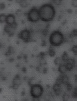
To make a clear comparison between the two techniques in terms of the quality after filtration and the number of bubbles, we use the example below:
Sample
Total flow rate 150 l/min, 0.5 gas fraction and 50 mm Submerged Length of cyclone.
Photoshop method
- Original frame
- Filtration frame by CS5 and determine number and size of bubbles.
b- MatLab Code method
- Filtration frame by MatLab and determine number and size of bubbles. This one frame from 10 frames.
Conclusion and Recommendation
A general analysis of the data analysis
Of the data collected concluded that the observed void fraction is strongly affected by the superficial gas velocity. This is because the higher the superficial gas velocity, the higher the observed average void fraction. This will then help in determining the size of gas bubbles produced in oil from a cyclonic inlet to a gas / oil separator.
However, there are some factors that affect the separation of fluids. They include:
- The minimum flow rate, the maximum flow rates, and the average fluid flow rate.
- The vessels operating and design temperatures and its forces per unit areas.
- The slugging tendency and the surging of the feed streams.
- The fluids mass per unit volumes and the compressibility.
- The foaming and the corrosive tendencies of the fluids.
References
Afanador E., 1999. Oil-Water Separation in Liquid-Liquid Cylindrical Cyclone Separators. Ph. D. The University of Tulsa.
Biker, M., 1953. Foams: Theory and Industrial Applications. Reinhold: New York.
Erdal, F., 2003. Local Measurements and Computational Fluid Dynamics Simulations in
A Gas-Liquid Cylindrical Cyclone Separator. Ph. D. The University of Tulsa.
Gomez, L., 2004. Dispersed Two-Phase Swirling Flow Characterization for Predicting Gas Carry-Under in Gas-Liquid Cylindrical Cyclone Compact Separators. Journal of Fluids Engineering 126(6), pp 1-8.
Mathiravedu, R., 2010. Control System Development and Performance Evaluation of LLCC Separators. Journal of Energy Resources Technology, 132(1), pp 1-9.
Movafaghian, S. et al., 2000. The Effect of Geometry, Fluid Properties and Pressure on the Hydrodynamics of Gas-Liquid Cylindrical Cyclone Separators. International Journal of Multiphase Flow, 6 June, pp 999-1018.
Ohnuki, A. & Akimoto, H., 1996. An experimental study on developing air -water two- phase flow along a large vertical pipe: Effect of air injection method, International Journal of Multiphase Flow, 22(6), pp. 1143-1154.
Shen, X., Mishima, K., & Nakamura, H., 2004. Two-phase distribution in a vertical large diameter pipe, International Journal of Heat and Mass Transfer, 48(1), pp. 211- 225.
Wang, S., 2000. Dynamic Simulation, Experimental Investigation and Control System Design of Gas-Liquid Cylindrical Cyclone Separators. Ph.D. The University of Tulsa.
Wang, S., 2003. Gas Liquid Cylindrical Cyclone (GLCC) Compact Separators for Wet Gas Applications. Journal of Energy Resources Technology, 125(1), pp 1-8.