Abstract
From the study, it has been found that there are many methods of bubble production. The choice of production method depends on the situation and application that the user desires. It is however not possible to recommend the best method based on the study but rather highlight the strengths and weaknesses of each method. Bubble characteristics are affected by the production method, purity/contamination levels of the fluid media, temperature, pressure fluid velocity, and surface tension. All these factors have been found to affect a bubble’s shape, size, and physical characteristics. The study of bubbles has been found to have useful applications in human life. One application that has been highlighted is in the foaming of oil. This is because the foam in oil is a major problem that needs to be addressed. Appropriate techniques that attempt to solve this problem have also been reviewed in the study.
Introduction
This research aims at determining the gas bubble sizes in a 2 phase and 3 phase fluid. In a two-phase flow, there exists a gaseous and a liquid fluid whose separation is a meniscus. This type of flow is very common in nuclear power plants and steam turbines. An understanding of 2 phase flows is important to understand the causes of failures in engineering pipes, heat and pressure losses (Salomon, 1999). A three-phase fluid flow involves the movement of fluid in three states namely, liquid, solid, and gas in a system. Examples of a 3 phase system are; a slurry reactor that is aimed at converting fluids from gaseous to liquid form and conversion systems for natural gas (Saleh, 2002).
A bubble can be defined as a pocket of one substance in another substance; the two substances are in different states. Bubbles however simple are very useful and at the same time harmful to man’s activities. Though unrecognized bubbles have many uses such as; increase the contact surface area in gas-liquid turbines, helping in the assimilation of atmospheric carbon dioxide into the ocean thus reducing the activity levels in the atmosphere and modern-day printers. Even though bubbles are useful to a man they also cause resistance to fluid flow, pressure, and energy losses (Tabakova and Zapryanov, 1998).
The major inlet device in this experiment will of a cyclone mechanism. A cyclone is a piece of equipment that serves to separate solid matter from a fluid suspension. A cyclone works using as a centrifugal vortex that generates a turbulent flow that allows matter to exist in three states i.e. gaseous, fluid and liquid. The advantages of using a cyclone as a bubble generation supplier are; the cost of maintenance of cyclones is low, they are simple to set up, are cheaper to install, and work best at high temperature and pressure (Yang, 2003). The performance of a cyclone is measured by the pressure difference and the efficiency of the collection of the cyclone. These characteristics can be improved by making modifications to the geometry of the cyclone; changing the length of the vortex and the diameter of the tip of the cone (Yang, 2003).
For bubble sizes to be determined, high-speed cameras must be used to capture the bubbles. High-speed cameras use electronic components such as CMOS (Complementary metal-oxide-semiconductor), CCD (charge-coupled device), and capture frames at a very high rate. The data is then stored in an inbuilt DRAM (Dynamic random access memory). The images from the high-speed cameras are analyzed using high-level programming languages such as C++ and math lab to enable the researcher to determine the bubble sizes (Annamalai and Kanwar, 2002). C++ is however preferred in many data analysis operations because it can be easily integrated for both hardware and software operations.
Various methods of generating bubbles will be assessed in the research and an in-depth understanding of each created. Methods of measuring bubble sizes will also be assessed in the study and this will attempt to enlighten on the various methods of bubble production and measurement. The study will attempt to answer several research questions:
- Which methods are available for bubble production?
- What are the strengths of each method?
- What are the weaknesses of each method?
- In which ways can bubble sizes be measured?
- What are the practical and economic implications of each method?
- What are the recommended improvements?
- Are there any new inventions in the field of bubble measurement and production?
- What are the recommendations based on the study.
This study aims at contributing to the knowledge of bubble measurement and production. A collection of works from different authors on bubbles in an engineering context will be analyzed and appropriate conclusions made based on the collected facts. Data from the different studies will be assembled and moderated to formulate a specific conclusion.
Methods of Bubble Generation
There are different methods of bubble generation that depend on the researcher’s choice. They have different types of production equipment, velocities required, set up costs, operating parameters, and bubble properties. A researcher’s choice of bubble production equipment depends on personal preferences, bubble characteristics required, financing required and equipment available. The major difference between the bubble production techniques is in operating principle as each has different mechanisms of operation This chapter will address and create insight on the different methods of bubble production.
Pressure-pulse bubble generator
One method of bubble generation is called the pressure-pulse technique. This is a relatively new method of bubble generation that has been in the introduction and test stages in the last decade (Lee, 2003). This method involves the use of electronically controlled pressure pulses that are injected into a fluid to generate bubbles.
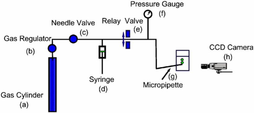
A major problem in bubble generation has been the inability to produce small bubbles due to the uncomfortably high pressures that are created at the orifice. The pressure pulse system offers a solution to this problem by cutting the pressure feed pipes to the bubble immediately it starts to grow using an electronically controlled relay. A front that creates a disturbance in the liquid-gas system results in the formation of microbubbles. Bubble sizes in the pressure pulse system are manipulated by changing the pipette and pressure levels of the system (Masliyah et al., 2003).
The working mechanism behind the pressure pulse generator is very simple; due to the pressure increment inside the bubble, it steadily grows in size until the pressure level reaches a maximum where the radius of the pipette equals the radius of the bubble. At this point, the bubble forms a sphere and is at its smallest radius. If the bubble exceeds this point there is a drastic loss of pressure and the bubble breaks off from the pipette tip (Hallowell and Hirt, 1994).
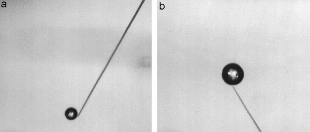
Certain factors have to be kept constant in the course of the bubble production procedure when using this method such as bubble pressures, gas viscosity, length of the taper, and the inclination of the pipette. Limitations of this bubble production method are; high cost of equipment, complex operation mechanism, and difficulty in attaining accurate bubble sizes due to the many factors that have to be kept constant (Lee, 2003). Its advantages are; bubbles of very small sizes can be produced, high bubble production rates are possible and simple concepts of operation.
Micro-hole bubble generator
This method involves the production of bubbles by the means of a submerged hole of microscopic dimensions. The bubbles were generated when a certain threshold pressure was attained. The threshold pressure was reached as an effect of draining liquid outside of the test chamber of the bubble generator. In the micro-hole generator, the flow of gaseous fluid through the hole does not assume a constant flow or pressure. This effect is caused by the pressure differences between the atmosphere and the bubble generator (Cowger, 1992).
Factors that affect the operation of the microbubble generator include; length/diameter ratio of the micro-hole, gas chamber properties, and the liquid drain rate from the chamber. Newer modifications to the earlier micro-bubble generator have been made to improve the ability to measure bubble volumes. This is done by the use of a two-stage model that replaces the earlier single-stage model.
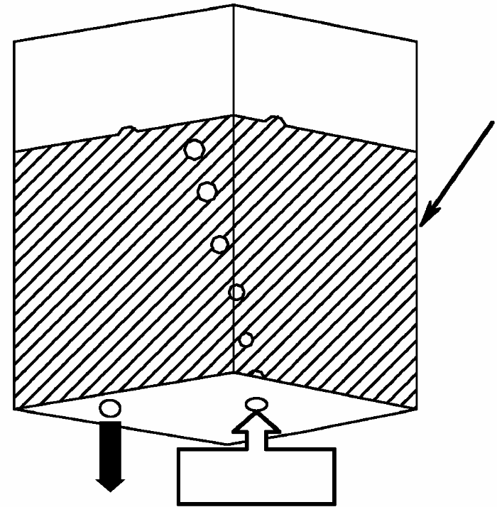
Calculations to help in bubble production are done in three ways; calculations for the growing bubble are done, calculations are done for the detachment stage of the bubble and the criterion for bubble detachment is calculated. These calculations enable the researcher to determine the appropriate bubble sizes and intervals that he desires to be produced by the generator.
The micro-hole bubble generator is used in various applications of our day-to-day lives. An example of the micro-hole bubble generator in practical life is the inkjet printer used for nonimpact printing systems. Such a system requires a carefully mapped out system that is to deliver ink to the print medium at the required proportions and quantities to attain a clear print (Sheu and Shyu, 2005).
Micropipette with ultrasound generation
This type of bubble generator works when an ultrasound frequency is applied to a very small pipette that serves as a mixer to distribute bubbles in a channel of flow. The ultrasonic frequency is imparted to the channel by the means of a piezoelectric transducer. The bubbles in this type of generation result as a result of a shearing effect when the ultrasound frequencies exceed 50 Vp-p (Leighton, 1997).
This type of bubble generation must eliminate the effects of inertia on the bubble production mechanism. The inertia effects are a result of the flow of the fluid in the microchannel. Mixing action is also present in the setup as it contributes towards increasing the surface area of contact of the gas and liquid particles with the micropipette. Bubbly flows are also artificially affected to create a high surface/volume ratio of the gas and fluid particles with the pipette. The ultrasound generator is known for its ability to do refining the two fluid phases i.e. gas and fluid and thus produces microscopic bubbles. The size and closeness of the bubble particles can be altered by changing the ultrasound frequencies that are fed to the generator (Thrush and Hoskins, 2003).
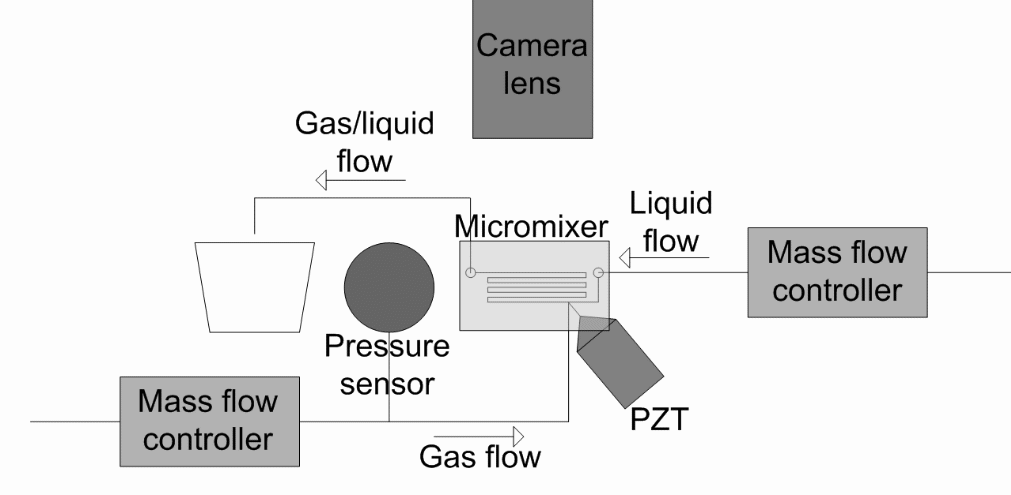
Applications of two-phase bubble generation using ultrasound frequencies include thrusting mechanisms for outer-space satellites. The reason for the use of ultrasound technology is that it is accurate and precise. It is also relatively easy to manipulate compared to other generation techniques. It is however very expensive to implement and thus is only used in high-level operations in NASA and Army operations (Thrush and Hoskins, 2003).
Tip streaming bubble generation in viscous flows
The tip streaming method is used to produce microscopic-sized bubbles in viscous fluids by the use of an electronically controlled jet operating at very high speed. This generator consists of two tubes; the outer tube that contains a more viscous fluid (often a liquid) and an inner tube that injects small amounts of a less dense fluid (often a gas) into the moving fluid.
The average size of the bubbles in this generator is 10 % the diameter of the streaming nozzle. The bubble properties are affected by the flow rate, nozzle size, gas injection pressure, pressure release time, and fluid properties. The setup of this generator involves two coaxial tubes that are fed by two independent pressurized reservoirs. The rate of flow of the two fluids is electronically set to very refined values by the precision regulators to enable the user to attain the bubble size and population required. The stock dimensions for the outer and inner tubes are 800 µm 100µm respectively. A high-speed camera monitors the bubble movement and properties and relays the information to a computer where a user can be able to analyze, tabulate and interpret the results (Lee, 2003).
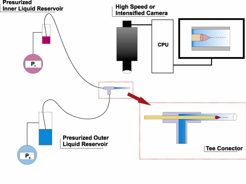
This type of generator is applied in many industrial applications due to its ease and simplicity of operation, simple geometry, and the ability of the generator to form a ‘multiplexed device’. Secondly, this type of generator easily works in all types of fluids and can operate even in fluids of high viscosity unlike other bubble generators (Lee, 2003).
Factors That Affect Bubble Characteristics
Various characteristics are used to describe the properties of a bubble. These characteristics are universal and are used to create an understanding of a bubble when it is being described.
The first property of a bubble is bubble formation. This covers the techniques that are used to form the bubble, the parameters present at the time of formation such as pressure, characteristics of the liquid in which the bubble is formed, types of orifices, stages of bubble development, the shape of the bubble throughout the formation stages and the dynamic forces at play (Darwin, 1953).
The second property is bubble shape. This refers to the physical arrangement of the bubble as it rises or flows in a fluid. Various factors affect the bubble shape such as the rate of flow of the bubble, the properties of the fluid in which the bubble flows, the pressure acting upon the bubble, temperature conditions in the fluid, and properties of the gas which forms the bubble. A bubble can be defined as spherical in shape, conical, oblate, and ellipsoidal. A bubble’s shape is usually a product of the balance of the tensional, buoyancy, and viscous forces that act upon the bubble. When a bubble increases in size it results in a shift of the balance between the above forces and the bubble changes shape from spherical to ellipsoidal and finally spherical. This is because for small bubbles the shape of the bubble depends on its inertia and tensional forces but as the bubble grows larger the inertia forces are stronger and the effects of the tensional forces of the fluid surface, viscosity, and fluid impurities become negligible. It is however noted that as a bubble tends to grow larger it flattens out; this is due to the pressure of the fluid that acts upon the bubble and creates a flattening effect (Tabakova and Zapryanov, 1998).
The third property is bubble rise velocity. Bubble rise velocity refers to the rate of change of a bubble’s upward displacement with time. This property is dependent on the bubble size. The general trend is that larger bubbles tend to rise faster than smaller bubbles. The bubble rise velocity is affected by the fluid properties in which the bubble is formed, the pressure and temperature of the formation environment.
Particle entrainment and drift are the fourth property of a bubble. A particle’s entrainment is affected by the wake behavior of the bubble. This is more pronounced in small bubbles compared to large ones. These particles also result in solid suspension distributions in the freeboard area. They are acquired from the top surfaces of the fluidized beds and are brought to the freeboard due to the effect of the wake at the bubble rear. Particle entrainment decreases as a bubble reduces in size and frequency. It also increases when the relative velocity between the bubble and the fluid increases and as the particle sizes grow larger. An understanding of the entrainment principle was created by Charles Darwin (1953),
“When a bubble emerges from a free surface of a bed a mantle of particles that cover the roof of the bubble drain away and rush into the rear wake of the bubble. Overall the particles move upward due to this near-wake capture as well as due to the drift effect.”
Interfacial surfactant contamination on bubble gas transfer
Interfacial surfactants affect bubble production as they suppress the transfer of gases in 2 phase medium. Control of these surfactants is difficult as they exist in most bubble production mediums in natural states. The term surfactant refers to chemical elements/compounds that lower the tensional forces of a liquid media. The surface intermolecular forces of a fluid decrease with an increase of surfactant concentration until the liquid reaches a CMC (Critical Micelle Concentration).
Surfactants increase surface rigidity of the bubble, drag coefficiency, and a decrease in terminal velocity (Shah et al., 1988). Research shows that as bubbles rise the surfactants are usually located at the bubble’s tail-end due to the ‘interfacial’ shear forces against the bubble. The Maragoni effect of bubble flow in contaminated fluids states that:
“Since a fluid with a high surface tension pulls more strongly on the surrounding fluid than one with a low surface tension, the presence of a gradient in surface tension will naturally cause the fluid to flow away from regions of low surface tension”
Surfactants result in the contamination of the fluid surface and result in a drastic reduction of mass transfer coefficients. The mass transfer coefficients of contaminated fluids have been recorded to fall below that of pure water to surfactants (Shah et al., 1988). Test results indicate that the surface tension of the fluid decreases gradually with an increase in the contaminant. When water is pure there is a uniform distribution of tensile forces and this results in a spherical bubble. As the contaminant levels increase the tensile forces gradually become weaker until they reach a minimum static value. For proper bubble formation, it is recommended that the fluid medium is pure and free from contaminations (Tabakova and Zapryanov, 1998).
Effects of magnetism on bubble size
Magnetic fields have been found to affect the bubble diameter, deformation of bubbles, and BSD (Bubble Size Distribution). This experiment aimed at understanding the effects of magnetism on bubble size is done using a frit and sleeve sparger. The sparger serves as a shear force control point and it regulates the sizes of produced bubbles.
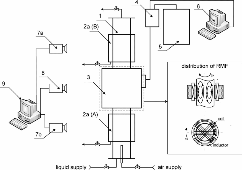
- Bubble container
- Rectangular containers
- a. Location A
- b. Location B
- Rotating magnetic field generation source
- A.C transistor (Inverted)
- Control box (Electronic0
- Central processing unit
- High-speed photo cameras
- High-speed video cameras
- Central processing unit with image analysis software
In this experiment, bubbles are generated from one end of a bubble generator and are made to flow from one point of the generator to another. As the bubbles flow, they pass through an axial magnetic field. This axial magnetic field is created by an electromagnet that is remotely controlled by a central processing unit. The central processing unit controls and varies the current to the inductor coils and thus magnetic field to enable the researchers to study the bubble characteristic variations with change in a magnetic field. A high-speed photo and video cameras are used to record the bubble characteristics. These cameras are attached to another central processing unit that analyses the images using image analysis software; Mathlab or C++
Results from this study show that in synthetic wastewater without any contaminants the bubble size increased proportionally with an increase in the rotating magnetic field values (RMF).In contaminated water ( with NaCl), the bubble size increment was however lower than in pure water. In the experiment, a dimensionless value named Hartman’s number (Ha) and Sauter’s mean diameter was used in the analytical stages of the experiment.
Measurement of Bubbles
Various methods are used to measure bubble flow behavior. There are two common methods of bubble measurement namely intrusive techniques and non-intrusive techniques. Intrusive techniques involve the use of optical fiber equipment, ultrasound equipment, hot films, and endoscopic probing equipment. The conductivity probe is used to measure the volume fraction of the bubble, relative velocity, and length of the bubble in 3 phase fluids. However for the probe to work the fluids must be of very high conductivity as it utilizes the conductivity difference in its mode of operation (Hoskins and Thrush, 2003).
Another measurement device for bubbles is the optical fiber probe. The basis of operation of this probe is that fluids transmit light effectively unlike bubbles which reflect the light. This probe however cannot be used in instances where there is a minimal refractive index between the gas and the liquid phases. For a precise reading to be achieved from the optical probe a high-speed camera is used to aid in the study. The optical probe is however advantageous as it can be used in conditions of high temperature and pressure where other methods would prove ineffective (Annamalai and Kanwa, 2002).
A hot-film probe is used to measure the point properties of a 2 phase fluid. This method is however not favored as it involves fragile equipment that cannot be used to measure bubble properties in media with high solid concentrations. It also requires a uniform temperature distribution throughout the measured media.
Nonintrusive bubble measurement techniques are those that can measure bubble properties without necessarily being immersed into the measured media. Examples of nonintrusive techniques include pressure transducers, x-rays, PET (Positron Emission Tomography), RPT (Radioactive Particle Tracking), NMR (Nuclear Magnetic resonance), Laser technology, and PIV (Particle Imagery Velocimetry).
The pressure transducers are usually placed on the bed’s walls and record the pressure changes. These changes are interpreted and used to reflect various bubble properties such as flow rates of the bubble, coalescence of the bubbles, bubble breaks up characteristics, bubble bursting characteristics, and bubble formation. Direct visualization techniques are used in systems that have low gas and solid holding capacities (Hoskins and Thrush, 2003).
X-rays are also commonly used in today’s science to investigate the bubble flow characteristics and determine the bubble shape, size of the bubbles, rise velocity of the bubbles, growth of the bubbles, and the breakage characteristics of the bubbles. The X-ray setup is made up of a beam generator that generates x-rays to pass through the media, an image intensifying unit, a video camera, and a central processing unit for interpreting the data (Tabakova nad Zapryanov, 2003).
Ƴ-rays are also used to assess bubble properties such as frequency, size, and coalescence of the bubbles. A difference between the radiation emitter and the detector is done by creating a relationship between the ionized gas and the detected radiations. The ƴ-ray setup involves an emitter that rotates around the fluidized bed. However due to its long scanning time the ƴ-ray tomography is used for studying the ‘time-averaged’ flow properties. It is unsuitable for measuring bubble formation and properties in fluidized beds.
Laser technology such as LD and PDA is used to measure the behavior of bubbles and identify the liquid velocities, the turbulence of fluid flow, distribution of bubbles sizes in the columns, and bubble sizes in three-phase fluids. A limitation of the laser technology is that it can only be applied to conditions that have a high gas hold-up.
Another technique of bubble production is the super-fast MRI technology. This method is widely used for 2 and 3 phase fluid floes e.g. trickle and movable beds. Common uses of this technology include analysis and operations on trickle-type bed reactors and quantifying the flow in bubble systems. This method has however encountered various difficulties in its implementation such as high cost of operation and unfavorable fluid property requirements. A strong advantage of this method is that it is easily modified to operate well in multi-phased fluids. This method boasts a high temporal resolution but lacks when it comes to spatial resolution (Tabakova and Zapryanov, 2003).
Measurement techniques
Video imaging
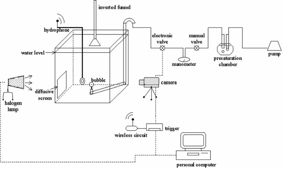
This is a measurement technique that makes use of sophisticated cameras and computers to measure bubble sizes. The camera operates at a very high resolution and is connected to an electronic valve that switches the camera on and off. The camera is triggered by pressure and is switched on once the bubbles are being produced and off when the production ceases. A computer is attached to the whole setup and serves to control the assembly. Light for the experiment comes from a halogen lamp that shines upon the water container. A diffusion screen is also attached to the opposite end of the container to prevent unwanted reflections and refractions. This method is preferred by most researchers as it is easy to set up and install.
Acoustic sensors
This method attempts to relate the detachment properties of a bubble to its inherent acoustic signals. Acoustic sensors are known for their very cheap cost of operation/purchase and their reliability. This method is also unaffected by the fluid properties of the fluid matter. Acoustic sensors are also used in bubble measurement applications that are not conducive and easy to reach due to their remote abilities.
In acoustic resonance the Minnaert value is given as:
V = (1 / (2 * π * rA) ) * SQRT ( 3 * ƴ * P) / ƿ
Where:
V = Frequency in Hz.
Π = value of pie 3.142
rA = the bubble radius
ƴ = specific heat of the gas that makes the bubble
P = Absolute pressure of the liquid
Ƿ = Density of the liquid
SQRT = Square root
Inverted funnel
A simple and common way of measuring bubble diameter is the inverted funnel technique. This method makes use of an inverted funnel (conical-shaped object). A capillary tube is also used to measure the length of the air column. A suction apparatus is applied at the top of the funnel and is used to suck the bubble into the tube. Calculations were then done based on the length of the bubble to estimate the volume of the bubble. This method is advantageous as it is economical and can be carried out with readily available materials. It is however not a very accurate method and allowances of 6% to 10 % are given for the volume change.
Foaming Oil
The science and art of bubbles are used in many fields in today’s world. The focus of this study is to investigate the use of bubble science in crude and oil separators. Various factors encourage the occurrence of foaming oil such as the composition of crude oil, turbulence, nozzle specifications, and presence of chemical elements such as nitrogen. The foam may also be encouraged by the emission of gases from the oil and high surface tension that locks in the gas bubbles
Foaming of oil is a major problem to miners and engineers as it causes pollution, damage to machinery and equipment, hinders the pumping abilities due to the locked gases, and can cause burning problems.
To solve the foaming problem a good understanding of the separator designs should be created. Cyclone devices could be used to reduce the fluid momentum by separating the liquid from the gas. This reduces the volume of the liquid and channels each into separate directions. Cyclones have been proven to reduce the momentum and optimize separation in 2 and 3 phase fluids. The main principle behind the cyclone is to create high centrifugal forces that in turn create high shear forces that break down the bubbles (Eakin and Vern, 1964).
Retention is another solution to the foaming oil problem. In this method, the oil is allowed to settle for some time and naturally release the held gases. This method is very cheap but time and space-consuming. Agitation using mechanical mixers is used to break the surface tension of the oil and to release the bubbles into the atmosphere. Heat can also be applied since as temperature increases the surface tension of the oil reduces and the gases can escape more freely (Eakin and Vern, 1964).
Chemical additives/contaminants can be added to the oil. This will result in a change in fluid and bubble properties of the oil and allow for easier release of the air bubbles. Silicon is the most popular de-foamer as it thins the bubble capsules and causes them to rapture.
References
Annamalai, K. & Kanwa, I., 2002. Advanced thermodynamics engineering. Washington: CRC Press.
Cowger, B., 1992. The Optimisation of Deliverable Ink from a Disposable Print Catridge. Proceedings of the IS & Ts 8Th International Congress on Advances In non-Impact Printing Technologies. The society of IS & T, VA, USA, pp. 312-317.
Darwin. C., 1953. Note on Hydrodynamics. Proceedings of the Cambridge Philosophical Society. 49, 342-354.
Eakin, J. & Vern, H., 1964. A Review of Well Stimulation and Techniques to Prevent Formation Damage in Oil and Gas Production. London: Info Circ.
Hallowell, C. & Hirt, D., 1994. Unusual characteristics of maximum bubble pressure method using a Teflon capillary. Journal of Colloid and Interface Science 168, 281 – 288.
Hoskins, P. & Thrush, A., 2003. Diagnostic ultrasound: physics and equipment. Cambridge: Cambridge University Press.
Lee, E., 2003. Micro drop generation. Washington: CRC Press.
Leighton, T., 1997. The Acoustic Bubble. Missouri: Academic press.
Masliyah, J., Xu, Z. & Najafi, F., 2003. Single microbubble generation by pulse technique. Alberta: Department of Chemical and Materials Engineering.
Saleh, J., 2002. Fluid flow handbook. New York: McGraw-Hill Professional.
Salomon, L., 1999. Two-Phase Flow in Complex Systems. Chicago: Wiley and Sons.
Shah, D. & Ginn, M., 1988. Surfactants in chemical/process engineering. Washington: CRC Press.
Sheu, T, & Shyu, J., 2005. Study on bubble formation at a submerged micro hole by a two-stage model. Journal of Chinese Institute of Engineers, Vol. 28, No. 5, pp. 859 – 858.
Tabakova, Z. & Zapryanov, Z,. 1998. Dynamics of bubbles, drops, and rigid particles. New York: Springer Publications.
Yang, W., 2003. Handbook of fluidization and fluid-particle systems. Washington: CRC Press.