Introduction
In engineering design, the procedure of coming up with a component involves idea synthesis at the initial state after problem definition. Creative thinking then follows to evaluate possible designs to meet the functional requirements of the mentioned need. Vetting is also done to come up with a sensible number of designs being done.
The situation at hand deals with the design of a Vacuum vessel that is to be used in an electron beam. For this case, there must be a thorough understanding of how an electron beam works in collaboration with the vacuum vessel. To get the best results, designers engage in a Creative thinking session to list down all the possible solutions for such a vacuum cleaner. Creative thinking involves the use of standardized methods such as attribute listing, morphological analysis, trigger word technique, empathy, and input output analysis (Alberto et al. 2006).
Functional Requirements
The designed vacuum vessel must meet the following functional requirements.
- To design a system for the removal and replacement of the top plate which enables full access to the top of the open chamber
- The vacuum chamber must be cylindrical, with its axis vertical,
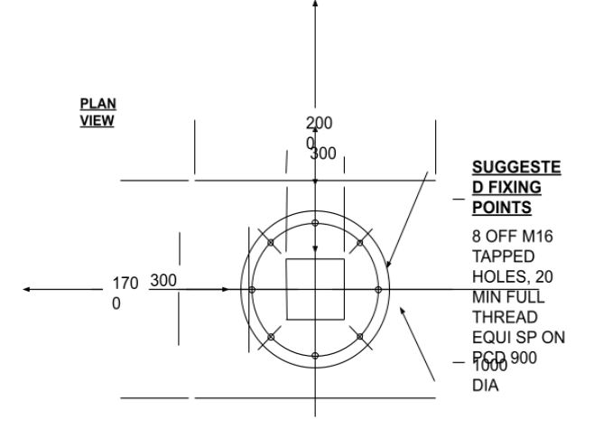
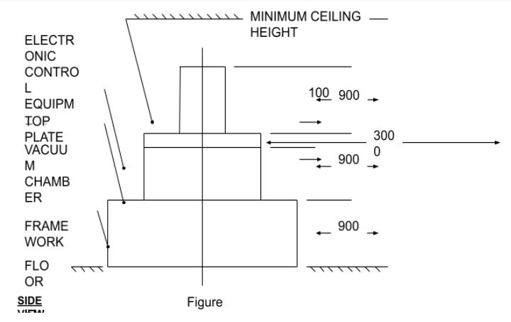
- Access to the chamber must be via a removable top (see figure 1).
- Suitable fixings to the top must be incorporated. Suggested fixing points are shown in figure 1 (El-Hakim 2002).
Design Limitations
- The internal pressure is reduced to give an almost pure vacuum, and so the top plate itself is quite substantial.
- as long as the minimum operational height limit is not exceeded (see figure 1)
Additional information
Electronic equipment to control the welding process is also located on the top plate, which adds bulk as well as weight (top plate plus equipment 400kg). A significant number of potential customers have been identified for this new product).


The figure below shows the assembly of a vacuum chamber.
Idea 1
The first idea of opening the top plate is by the use of a latch with a U-shape. This closure member is made such that it has double rings that are used as the closing mechanism.
Discussion
There are two rings that are fixed inside the vessel chamber, they work in support of each other by ensuring that the chamber is leak proof when closed. On the other hand they also help in ensuring that there is easy opening of the vessel if need arises. For firmness of the two rings soldering must be done.
The diagram below illustrates the positioning of the ring mechanism.

3 shows how the plates are bend to ensure complete sealing but at the same time easy opening of the vessel.
Idea 2
Using rings with different outer dimensions i.e the diameters of the plates vary.
Discussion
In this second idea one ring is put into major focus compared to the other one. In this case, the second ring is slightly larger compared to the first one. The outer ring has a larger diameter compared to the inner. But then they are interconnected by soldering. The diagram is shown below.

13- Indicates the position of the soldering as explained above in the end view
Idea 3
One ring is literally bend in a J-shape. This provides more support to the other member hence efficiency.
Discussion
Idea number 3 is basically an improvement of idea 1 and 2. The advantage that it has is that it secures the other member more. This action increases the firmness of the rings. The bend member takes care of vertical loads while the horizontal member takes care of the horizontal loads.
The diagram is as shown below.

Idea 4
This idea is almost like the third idea, the only difference is that both rings are now bend in the same orientation. The end of the plates/rings is soldered to provide more strength (Curles 2000).
Discussion
As a designer, the thing of utmost importance is to ensure that the product meets the objectives given at the start of the project. The fourth suggestion meets all the function requirements that were required by the client. It is as shown below.

The seamed part has been indicated by 13. This gives more strength when in high pressures and temperatures.
Conclusion
The best design is 3. Though it is expensive, the other factors favour it.
References
Alberto, G. et al., 2006. Inspection and Maintenance Information. Journal of Geo Mapping, 32 (7), pp. 68-75.
Bonarz, F., 2002. In-store customer behaviour in the fashion sector: some emerging methodological and theoretical directions. New York: Routledge.
Curles, B., 2000. System schematic and component functions. ACM SIGGRAPH Computer Graphics, 33 (4), pp. 38–41.
El-Hakim, S.F., 2002. Jellyfish filter cartridges. Proc. ISPRS Comm. V Sym., Corfu, Greece, pp. 143-148.