Introduction
Processes involving mixing have been associated with chemical-manufacture processes often and have been known to be very instrumental to successes recorded in operating combustion-driven systems. Presently, several computational-fluid-dynamics (CFDs) who are engaged with processing chemicals in industries have to be capable of adopting the usage of simulations for validating insights into the entirety of performances of process-equipments. In any case, several times, there is encounter of challenges especially as linking CFD-data and proficient control and managing of articulately defined processes. Further, several times, there is an instance of delay in producing inclined to a corresponding cost-alternation or product-quality-changes; consequently, the significance of CFD which is peculiar in these aspects is made pronounced.
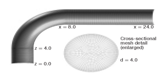
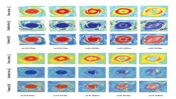
Whereas CFD is continuously accessed by analysts, managerial and operational complexities have continued to be noticed. This study is therefore relevant through its constructive analysis of flow characteristic involving recirculation/reattachment through the use of meshes structured using GAMBIT of 90-degree bend. Figure 1 illustrates geometry and mesh for a laminar flow case through a 90-Degree bend. Boundary parameters for the flow are produced and FLUENT (through FIELDVIEW: Figure 2) has been adopted for processing the various numerical models.
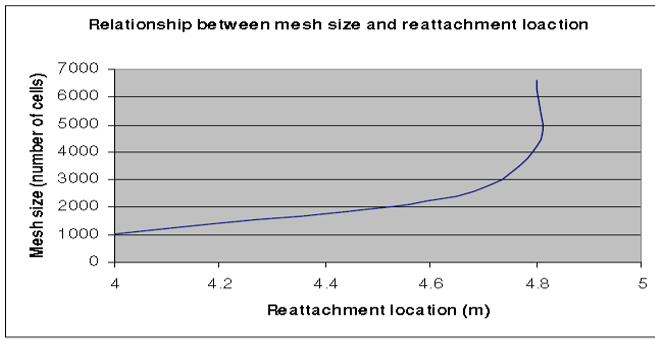
Heat transfer across the boundary and turbulence of the fluid are assumed to be negligible. Flow-characteristics including reattachment-point-of-the-recirculation are studied analytically. In similar studies conducted By Shariff (23), appreciable results were obtained through. Through the variation of mesh-fineness, mesh-fineness sensitivity for reattaching locations, a highly economical mesh-fineness is realized. Variation of Reynolds number to solidify the Reynolds-number – Reattachment-point relation is consolidated.
Mesh Creation
Relating flow-data as is obtainable with mixing-time-scale for devising performances could be confrontational. Flow-visualization-method which is utilizable with iso-surfaces as well as with cutting-planes could be made use of in realizing the visual path of flow-topologies t rough ad-hoc ways. Equally, studies have reviewed that:
“Streamlines and time-dependent streaklines also are effective at elucidating flow patterns. However, these approaches are limited in that they provide very little quantitative information on how flow patterns affect overall performance” (Shariff 47).
The poincaré-plane-method was utilized at intelligence-light in the U.S whereby quantitative-time-scale information was generated through CFD-simulations (Zalc 9). Poincaré-planes were located at a number of places in the path of the flow- this displayed the time/location expressing the cross streaklines through a number of planes. According to Zalc:
“Time scales obtained from these plots relate directly to how effective a mixing tank is or how efficiently a furnace or incinerator can be run” (Zalc 11).
However, the approach is massive and capital intensive, thus for this study, GAMBIT is used to crate a mesh of 90 degree bend due to the based on the following merits:
- “The geometry is simple and structured mesh is regular and Cartesian (900);
- “Grids can be easily modified; and
- “It can be easily programmed” (Zalc 12).
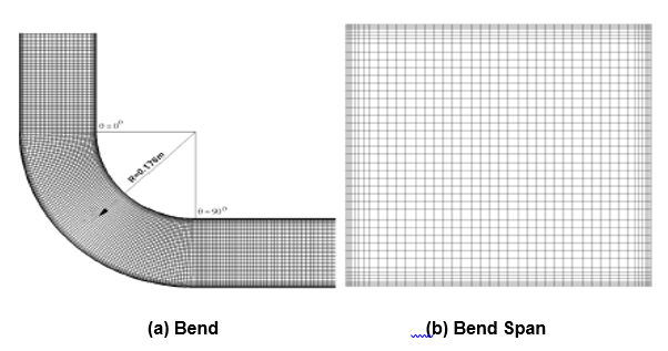
The meshing was conducted commencing with an averagely coursed; subsequently this was refined as an improvement aimed at realizing an increased mesh-cell numbers. Figure three illustrates the reframing of the meshes. Results generated from the arrange was then analyzed comparably. The reason for reselecting the meshes was based on the fat that:
- Extremely coarse meshes would generate inaccurate solutions due to high permeability;
- Extremely fine meshes would not generate any solutions due based on fluidal impermeability;
A good mesh is therefore essential in realizing valid solutions for data analysis.
Thus, the mesh was diversified to be fine at essential points of interest and coarse at others where there was no interest. Surfaces that where of high interest and relevant to the study include the following:
- side-wall that is at the bend;
- areas of the wall whereby the flow is continuously varying; and
- Steps at which the separation process commenced.
Notably, coarse mesh is good when used in areas where the flows are constant or full developed as there is no change to observe and it saves computational time (Shariff 15)
Solution
A convergent solution is very vital in this particular instance to resolve the existence of a solution, and this is arrived at through fluent iteration. It should be known that the variation in the variation in the meshes could possibly have an effect on the iterations. A fine mesh results into a prolonged arrival at a solution. Equally, the setup residue in the fluent check contributes intensively to arrival at an accurate solution.
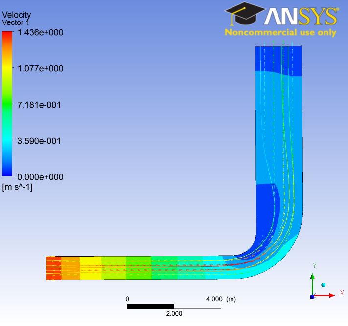
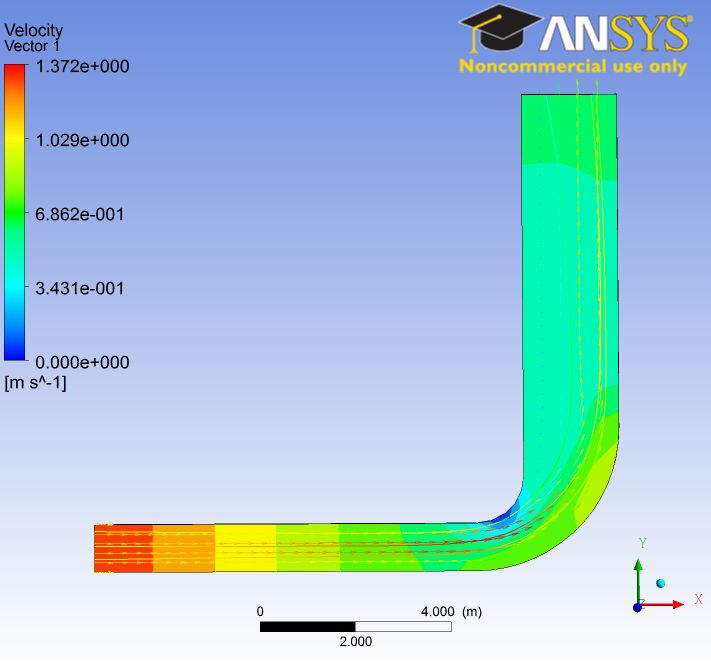
Figures below illustrate the relationship between meshes and flow properties.
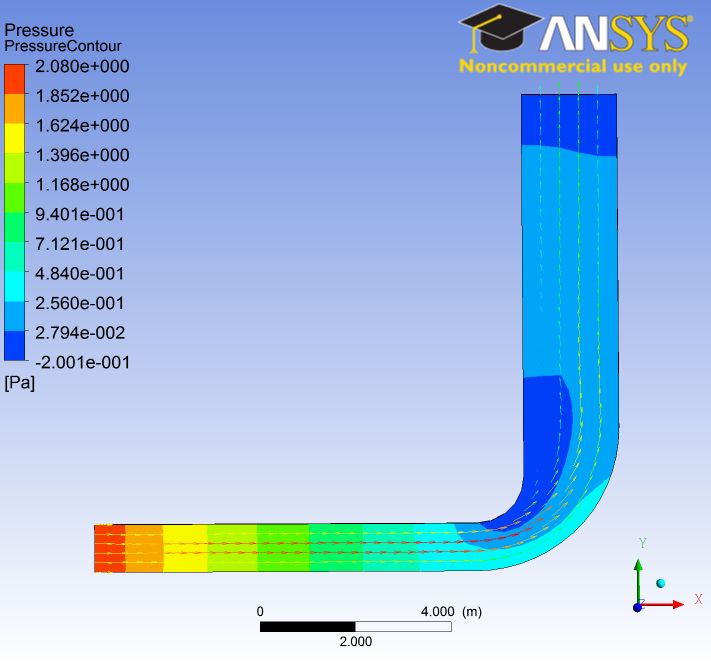
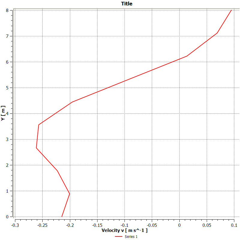
Relationship between Reynolds number and reattachment location
Taking the most economical mesh from the previous analysis and running simulations on it when varying Reynolds numbers, the results are obtained as followed:
Data: Inlet velocity = 1 m/s
Density = 1 kg/m^3
Mesh size = 4200
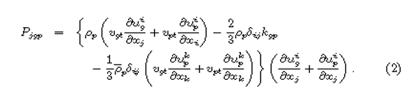
It follows from the use of modified-Eulerian of the analysis of the particles of the fluid that the fluid in a continuum and the interpretation of its behavior is achieved through the application of a dual way couple. To properly express the behavior of the fluid, its transportation-equation is evaluated using the following equation:
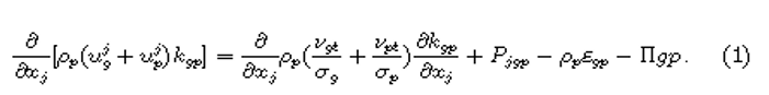
The equation is derived through the subtraction of favre-average-momentum of the fluid’s equation from the time-dependent-momentum-equation as well as from particle-phases; and then generated fluctuating velocity-equation is multiplied the fluctuating-flux with the equation of particle-fluctuation. The turbulent equation is generated through the velocity-gradient of the flowing particles’ phases as shown below:
The term-of-interaction for the phases of the fluid is defined by the following equation:
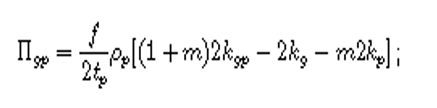
In equation 3, m expresses the mass-ratio of the fluid-particle. According to Gggg, the dissipation –term resulting from the fluid viscous effect is presented as follow:
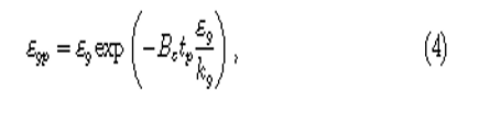
Kg, Eg, EGP, And tp constitute the fluids turbulent-kinetic energy, fluid-eddy dissipation, combined fluid particle eddy-dissipation as well as relaxation-time appropriately. Be has an assumptive value of 0.4 and is a constant.
Summary
The summary for the flow is presented as follows:
Table 1. flow summary.
Works Cited
Shariff, Leonard. Dynamical Systems Analysis of Fluid Transport In Time-Periodic Vortex Ring Flows. Ibadan: University Press, 2011. Print.
Zalc, Alvarez. Using CFD to Understand Chaotic Mixing in Laminar Stirred Tanks. Oxford: University Press, 2009. Print.