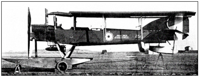
Short N.2B Seaplane (1917)
Short N.2B seaplane was first launched in December 1917 during the First World War in the Rochester manufacturers also known as the Short Bros Ltd in Britain. Francis Webber who was being supervised by Oswald Short designed the first seaplane which was tested at Marine experimental aircraft deport. The Short N.2B was designed as a way of outdoing the Wight Converted Seaplane and the Fairey, which were in the market during the 1917s. During its design, Oswald wanted to use the Rolls-Royce Eagles engine, which the other planes used, but it was not possible due to the shortage of the engines in the market. The Short N.2B prototypes used the Sunbeam Maori I engine of 260hp (Bruce 1957).
The Short N.2B was therefore designed with one 260hp Sunbeam Maori I engine, which was cowled fully with the cooling louvers together with a frontal radiator. The first two completed seaplanes with the Maori engine did not prove to be any better than the Short type 184 which it was supposed to replace. The two seaplanes had two-bay biplane, two-seat, and two main floats. The seaplane was 40 feet 2 inches lengthwise and its height was 13 feet and 9 inches. When empty the plane weighs 1,481 kg and when loaded it weighs 2,232kg meaning it could carry many weapons (Barnes 1967).
I preferred the Short N.2B because of the size of its wings where the wing area was 63.0-meter square, a wing space of 55feet and 2 inches, which is equal to 16.82 meters, and a wing loading of 35.4 kilograms per square meter (Mason 1994).
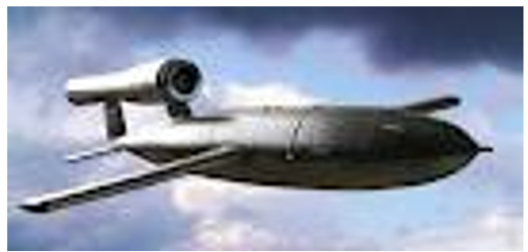
V-1 Flying Bomb (1994)
The V-1 flying bomb was also known as the Vergeltungswaffe eins, buzz bomb, or the anti-aircraft was launched during the First World War to compete with the V-2, which was costly as compared to the V-1 flying bomb. Dipl-Ing Robert of Fieseler designed the airframe of the V-1 flying bomb under the guidance system of Siemens. This prototype was later manufactured by other factories like the Mittelwerke, Henschel, and Volkswagen. The flying bomb was first tested in 1943 and was later launched by Reichsmarschall Hermann during Christmas Eve of 1942 and later Wachtel Max engaged his armies in firing the bombs against England (Holsken 1994).
The launch crew of the V-1 would load aviation fuel into the tanks after which it had to attach the wings of the flying bomb to the fuselage. The crew could also load the flying bomb on the launch ramp and it had to attach the catapult properly to the missile before launch. The flying bomb flew 3,000 feet in its normal state at 400 miles per hour and this was its maximum speed. The controlling surfaces deflect by tipping the missile downwards facing the earth and this could happen when the bomb had attained the range that was set. This caused the choking of the engine hence its quit (Neufeld 1995).
The pulse jet engine of the V-1 flying bomb is one of the features that were easily noticed due to its physical and audible characteristics. The engine always provided the force that thrust the bomb propelling it to the targeted direction. The pulse jet engine was placed outside the fuselage and above the tail of the plane. When the engine could start, the flaps opened up allowing the air into the combustion chamber hence mixing with the fuel. This combustion process made the engine to produce the duv-duv-duv- sound (Maj C.R. 1945).
I preferred the V-1 flying bomb because of its simple jet engine, which could accelerate the speed of the flying bomb up to 400 mph. The position and size of the wings were also good as it enabled the easy and faster movement to allow air into the engine.
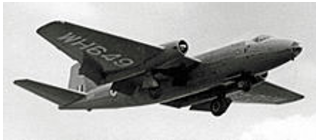
Vickers Valiant BMK.1 (1955)
The Vickers valiant first known as the Canberra was established during the First World War by the royal army in Britain. The V-valiant had its origin in 1944 as a high-speed bomber in high attitude without any defensive armament. The English electric is the company that was appointed to develop the V-valiant. The Canberra was first designed as a twin-engine flying bomber, which was an imitation of the two fuselage-mounted engines of the Metrovick F.2/4, which made the authorities doubt its efficiency since the two fuselages mounted engine operated in low altitude while the Canberra was meant to operate in high altitudes (Buttler 2005).
Sir George Nelson who was the chairperson of the English Electrical company first launched the Canberra. The Canberra was therefore designed in a simple way, which resembled a Gloster meteor scaled-up with a wing. The fuselage had circular tapering at both ends as the cockpit was placed aside in such a way that it had no protrusions and the wings were separated with the tubular engine. The Canberra was jet-powered just like the V-1 flying bomb though its shape was more of a mosquito mold hence increasing the capacity to load more bombs and therefore able to fit the two most powerful engines in a compatible and aerodynamic way (Beamont 1996).
I preferred this kind of aircraft because of its size and the type of engine is used. The engines of the Canberra were powerful in that they were of the Avon R.A.3s, and they could propel the movement of the flying bomb at a speed of 871 kilometers per hour. It had a service ceiling of 14, 600 meters, and could carry weapons weighing 3.6 tonnes. The design and size of its wings were also appealing since it gave it a better shape. The tanks, which were shaped like a teardrop, were placed under the wingtips where they fitted perfectly (Buttler 2005).
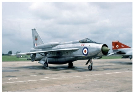
English Electric Lighting F.MK (1960)
The English electric lighting is one of the supersonic aircraft that was designed and manufactured in Britain. This was the first single-seat fighter that was manufactured in Britain and it was in operation for more than 25 years without any failure in its performance. It is therefore one of the aircraft that many pilots enjoyed flying though in its development some complications affected its exportation greatly. Its design started in 1948 after the cancellation of Bell X-01 in 1947. W.E.W Petter who was the chief designer of the English Electric company designed it in May 1949 (Bowman 1997).
The aircraft had two engines, which were housed in the fuselage where one was placed on top of the other. The lower engine was placed beneath the wing box structure, which was at the center as the other engine was placed just behind the wing. This kind of arrangement consumed the larger position of the fuselage whereby the jet pipes and the intake ducting took up the larger volume leaving very little space for fuel. The wing of the electric lighting was designed in such a manner that it served as a tank since there were no other separate bag tanks. During the wind tunnel tests, the design of the aircraft proved to be promising (Lake 2006).
During its development, the designer made changes after each test to ensure that the required features were attained. Due to such kind of changes, the aircraft remained in operation throughout the years without being canceled even when other fighter bombs were canceled from the operation. For example, when Duncan Sandys the defense minister canceled the operation of most fighters the English electric had already been developed in such a way that in the upper nose there were two Aden guns and a bulged ventral hence providing more room to accommodate another fuel tank. The WG760 was later fitted together with an afterburner, which looked simple, and during its test, it could reach a speed of Mach 1.53 (Lake 1997).
I, therefore, like the English electric because of the way the Avon 210 engines were arranged and fitted with a fully reheat system. The fuselage was also modified in a better way that the cockpit was raised and this gave an all-around overview for the pilot. The size and position of the wings were also good because they gave the aircraft a better look ((Lake 2006).
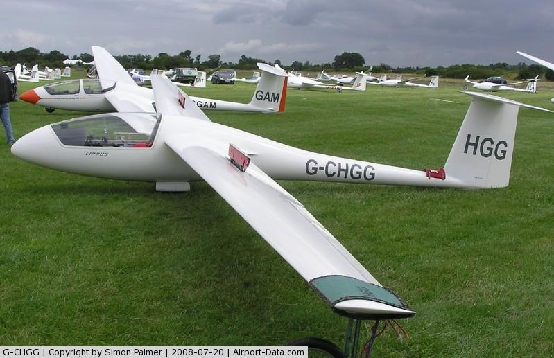
The Schempp-Hirth Cirrus (1973)
The Schempp-Hirth was initially founded as the Astir in 1970 and later developed as an offspring of Grob Maschinenfabrik in 1971 and 1975; it was developed under the license of Schempp-Hirth. The construction of the Schempp-Hirth began in 1973 and its first flight took place in December 1974. The Schempp-Hirth was designed by a group of engineers under the supervision of Professor Richard Eppler. The aircraft was therefore designed in such a manner that its wing featured a high area of 12.4 square meters, which seemed unusual. Its design partly featured the characteristics of the Eppler 603 profile. It, therefore, had a high speed, which was optimized though with the controlling characteristics of low speed (Arnold and Eaker 1986).
Wolf Hirth and Joan Price first flew the Schempp-Hirth during the National British contest in 1985. The wing sweep that had the design of the Eppler design was later rejected and this led to its redesigning by enlarging the canopies. The Schempp-Hirth was designed with a long fuselage with an improved layout of the cockpit and some features of weight saving. The wings were later reduced and its elastic flap was the unique feature in it. The fuselage was later redesigned to one canopy to reduce the drag. Its wing loading was 31.49 kilograms per square meter and the aircraft had a gross weight of 570 kilograms (Buttler 2005).
I preferred the Schempp-Hirth 1973 because of its design that had a Revmaster engine and its landing gear, which was semi-retractable, and the way the two seats were placed side-by-side. Its approach control was guided by the surface brakes, which were placed at both the top and the bottom. The Schempp-Hirth had a pusher propeller of two blades that were of a Hoffmann. I also liked its size since it covered an area of 18.10 square meters (Arnold and Eaker 1986).
References
Aeroflight Company, 2012, English electric lightning. Web.
Arnold, H & Eaker, I 1986, This flying game, 2nd ed, Funk and Wagnalls, New York.
Barnes, C 1967, Shorts aircraft since 1900, Putnam, London.
Beaumont, R 1996, Flying to the Limit, Patrick Stevens Ltd, Somerset.
Bowman, M 1997, English electric lightning, The Crowood Press Ltd, Wiltshire.
Bruce, J 1957, British airplanes 1914-18, Putnam, London.
Buttler, T 2005, British secret projects, Jet fighters since 1950, Midland Publishing, Hinckley.
Hosken, D 1994, V-missiles of the Third Reich, the V-1 and V-2, Monogram Aviation Publications, Massachusetts.
Lake, J 1997, ‘English electric lightning’. Wings of Fame, vol. 7, pp. 36-101.
Lake, J 2006, ‘Aircraft profile – English electric lightning – Part Three’, Air International. vol. 70 no. 3, pp. 64–66.
Maj W 1945, ‘V-weapons (crossbow) campaign’, US Strategic Bombing Survey, vol.9 no. 24.
Mason, F 1994, The British bomber since 1914, Putnam, London.
Neufeld, M 1995, The Rocket and the Reich, The Free Press, New York.