Abstract
The reason that this case study is to educate on the scheme, modeling, process and usages of the regulated power supply which simply is an essential structured block of many electronic arrangements that we come across in everyday life such as in mobiles and laptop chargers, entertainment as well as many consumer microchip technology related items as well as portable biomedical devices.
Important acknowledgments when specifying power supplies are the sorts of output whether regulate or unregulated. The former means that the voltage will remain stable for at least while the supplied current is operating within its specifications, regardless of the load. Unregulated supplies usually have higher electric outputs than usually stated and normally they are used with devices that have their own internal regulating electrical system. According to Distels Waters (2008),
Using voltages that are exceeding than recommended for a particular part of equipment can cause perpetual destruction. Where wattage or VA rating is mentioned this rather refers to the total wattage available for that power supply. This figure is mostly used for multi railing pieces, so that when the VA is calculated for each output and then added together, the total Wattage / VA does not exceed the makers’ rating (n. p.).
Introduction
In this section, we define the notion of a simple power supply with a block diagram and a simple description of important subsections (e.g. transformers, rectifiers, etc). We will also briefly mention the classification of different types of power supplies – their key characteristics, advantages / disadvantages and applications.
Now, a regulated power supply is an inserted section, or standalone piece, that functions as a supply of a stable voltage (or less often called current) to a unit piece or device that must be workable within a certain power supply boundaries. The output of that regulated power supply may be changeable or in one direction flow, but is nearly always a DC (Direct Current). Now a DC can be unregulated and may control circuit of a current, however, that becomes unreasonable when the source varies continuously or at a wide range. A regulator simply provides less power necessity but at a dependable level despite the matter of the source swing, i.e., fluctuation.
This is much more common today,
A D.C. variable bench supply (or rather known as a bench power supply) usually refers to a power supply capable of supplying a variety of output voltages useful for bench testing electronic circuits, possibly with continuous variation of the output voltage, or just some preset voltages; a laboratory (lab) power supply normally implies an accurate bench power supply, while a balanced or tracking power supply refers to twin supplies for use when a circuit requires both positive and negative supply rails), mobile Phone power adaptors as well as regulated power supplies in appliances (Gates Energy Products, 1992, p.14).
In accordance with Gates Energy Products (1992),
Modern regulated supplies mostly use a transformer, silicon diode bridge rectifier, reservoir capacitor and voltage regulator IC. There are differing variations on this idea, such as units with multiple voltage lines, variable regulators, power control lines, discrete circuits and so on. Switched mode regulator supplies also include an inductor (p. 15)
Control of electricity supply is much more sophisticated. An example will be from a 1980s TV using a double-direction interface between the main unit and the out-coming electric line stage to make use of it (i.e, the electric current), making a variety of out-coming voltages with differentiated amounts of stabilization, and, since neither juncture could start without the other operating, the supply also includes a sort of “ignition” system to keep the system lively (i.e, working) in the process of the operation. The electric power supplies also detect the movement of voltages in the TV power circuits which shut down if these voltages ran off their designed for specifications. Under certain circumstances, particular applications, such as AKA supplies, can be presented in even much more sophisticated forms.
Circuit and Operation
For example, a 5V regulated supplies:
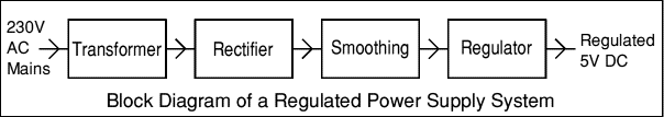
Each of the blocks is described in details as follows:
- The transformer lessens down ultra-voltage AC currents to low voltage AC.
- The rectifier carries out a conversion of AC to DC, another variable.
- Smoothing is a process that refers to passing of DC from high currents to the small ones.
- Finally, a regulator removes small currents by fixing the out-come DC current to a certain fixed voltage.
As presented by SGS-THOMSON Microelectronics (1995),
Some electronic circuits need a power supply with positive and negative outputs as well as volts equaling zero (0V) – meaning, at rest, which is called ‘dual supplying’ because they’re like two ordinary supplies linked together.The low voltage alternating current outsourced is suitable for lamps, heaters and special same like motors. They are not suitable for electronic circuits unless they include a rectifier and a smoothing capacitor (n. p.).
Transformer + Rectifier
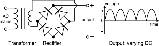
The differences that occur in direct current outcomes are suitable for lamps, heaters and standard motors, not for electronic circuits unless smoothing capacitors are included (SGS-THOMSON Microelectronics, 1995).
Transformer + Rectifier + Smoothing
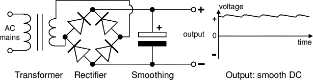
The smooth DC output has a small wave current and is suitable for most electronic units (SGS-THOMSON Microelectronics, 1995).
Transformer + Rectifier + Smoothing + Regulator
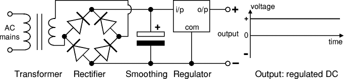
The controlled DC productivity is very plane with no wave. It is appropriate for all electrical paths. Convertors operate only with alternative currents and this is one of the explanations for why main power is an AC.
Converters amplifying voltage level are called step-ups; those converters that reduce voltage are referred as to step-downs. Irving (2011) suggests,
The feeding coil is called the primary and the output coil is called the secondary. There is no electrical connection between the two coils; instead, they are linked by an alternating magnetic field created in the soft-iron core of the transformer. The two lines in the middle of the circuit symbol represent the core. Transformers waste very little power so the power out is (almost) equal to the power in. Note that as voltage is stepped down current is stepped up. The percentage of the number of turns on each coil, called the turns’ ratio, defines the proportion of the voltages (p. 19).
Rectifier
Rectifier can adjust an alternative current to the direct one through linking diodes in different ways. Bridge rectifier creates a full current altering DC and, therefore, it plays a crucial role in the process. A full-current rectifier can also be made of just two diodes if a center-tap converter is used, but this method is infrequently used now that diodes are inexpensive. A unit diode may also be utilized as a rectifier in case applying positive (+) parts of the alternative current movement aimed at creating half-wave current changing the direct one.
Smoothing
Smoothing is carried out with the help of a large charge electrolytic capacitor that is connected with direct current acting as a pool and supplying output when the changing direct voltage of the direct current from the rectifier decreases. The diagram presented below provides the unsmoothed direct current and the smoothed one. The capacitor charges at the peak of the changing direct current. Further on, it discharges when it supplies the output (Discover Circuits, 2011).
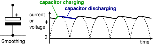
Note that smoothing augments the mean DIRECT CURRENT voltage to almost the peak value. For example, 6V RMS AC is amended in accordance to direct current reaching 4.6V RMS, along with smoothing rising up to almost the highest level providing 6.4V of smoothed direct current.
Smoothing is not terrific because of the capacitor power failing a little as it releases energy giving a small wave current. For many circuits a wave which is 10% of the supply voltage is suitable. The value of the capacity must be increased twice while smoothing direct current of a half-wave type.
Zener diode regulator
As presented by Discover Circuits (2011),
For low current power supplies, a simple voltage regulator can be made with a resistor and a zener diode connected in reverse as shown in the diagram. Zener diodes are rated by their breakdown voltage Vz and maximum power Pz. The resistor limits the current. The current through the resistor is constant, so when there are no output current all the current flows through the zener diode and its power rating Pz must be large enough to withstand this (n. p.)
Example: output voltage required is 5V, output current required is 60mA.
- Vz = 5V (nearest value available)
- Vs = 9V (it must be a few volts greater than Vz)
- Imax = 77mA (output current plus 10%)
- Pz > 5V × 77mA = 385mW, choose Pz = 500mW
- R = (9V – 5V) / 77mA = 0.05kΩ= 50Ω, choose R = 50Ω
- Resistor power rating P > (9V – 5V) × 77mA = 308mW, choose P = 0.5W
Design and Simulation
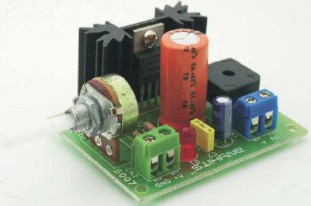
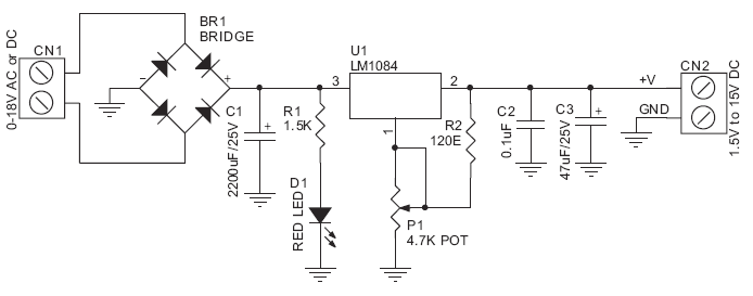
“This kit provides a variable output power supply ranging from 1.2 to 15 V @ 3 A. It uses Low Dropout Positive Regulator LM1084 in TO220 package for delivering variable output voltage.
- Input – 18 VAC/DIRECT CURRENT
- Output – variable output from 1.2 ~ 15 V @ 3 A Regulated low ripple DIRECT CURRENT voltage
- Heatsink for regulator IC
- On board bridge rectifier to convert AC to DIRECT CURRENT
- LED indication at input of IC
- Zener trimmed band gap reference, current limiting and thermal shutdown (provided by IC feature)
- Power Battery Terminal (PBT) for easy input and output connection
- Onboard PCB mounted Potentiometer (POT) for varying the output voltage
- Filter capacitors for low ripple DIRECT CURRENT output
- Four mounting holes of 3.2 mm each
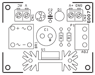
- PCB dimensions 46 mm x 58 mm” [Discover Circuits, 2011]
Schematic process
Conclusion
An inappropriately performed power tool is quite a quite complicated component to define. Therefore, it is commonly introduced while working on solving hardware problems at first. However, when using a reliable multi-meter, they can quickly check the links for proper current flow measurements. The main point of power supply problems is in the power input, so, when you move on testing these areas as explained before, you should be able to tell the functionality of the power supply as the malefactor.
References
Distels Waters, 2008, Power Supply. Web.
Gates Energy Products, 1992, Rechargeable Batteries Applications Handbook, US: Butterworth Heinemann.
Irving M. Gottlieb, 2011, Regulated Power Supplies, US: Tab Books. Web.
Leads Direct, 2010, Power Suppliers. Web.
SGS-THOMSON Microelectronics, 1995, Power Supply Design Basics. Web.