Introduction
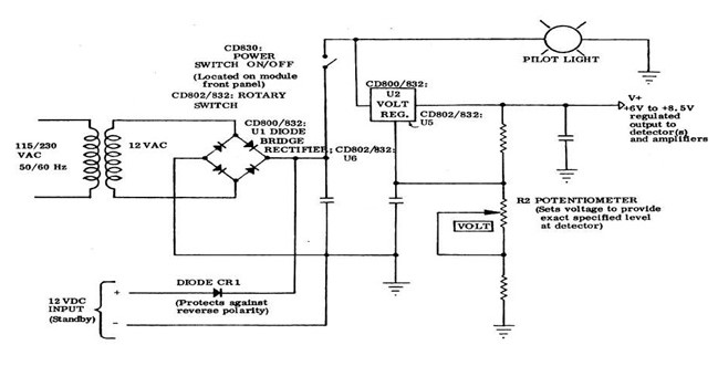
The power supply unit in electronics is the central unit that provides a load within the system-controlled power. Essentially, the supply unit gets its power from the mains; it then rectifies the AC power input through a series of rectifiers made from a combined circuitry consisting of transistors, resistors, diodes, and capacitors. In the design process of the power unit, these electronic components are fundamental. The photograph below shows some of the most basic parts of a computer power supply unit. The power supply unit consists of a feedback system that is responsible for maintaining the control of power after the rectification process is completed (Gillespie, 2004). The transformer inside the circuitry is designed to control the power reduction normally called the step-down; this enables electronic devices to comfortably use the power source without affecting their functionality because of over current. A complex schematic representing a simple computer power supply unit is as shown in the figure below.
A foundational design theory
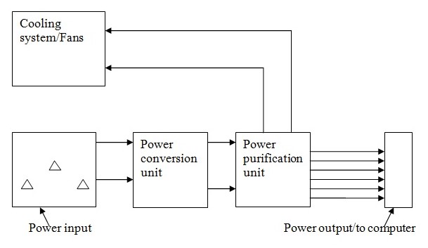
The design of a power supply unit to be used in a computer will consist of four basic units as follows; power unit, power converter, power purification, and cooling unit (Malmstadt, 2004).
Power unit
This is the section of the power supply that will be connecting to the main supply unit of usually about 250 V in the voltage rating of the external power supply (Wigmore, 2001). The three ports shown in the power unit are the live, neutral,l, and earth in a typical socket usually terminated inside a building.
Power converter
This functional unit of the power supply will be responsible for the conversion of the power source AC to DC (Oklahoma, 2007). It will be made up of integrated circuit and a cooling system. The resistor in this unit will regulate the current flow according to the specification. The capacitors in this section will be responsible for power storage. Diodes and coils combined with the transistors will enhance the smooth conversion of the AC to DC by setting limits to the sinusoidal waveform output.
Power purification
The power purification unit will also be made of a series of integrated circuits and resistors that will ensure only the required amount of current passes through to the load (computer). The load, in this case, is the computer, the limitation of power is meant to restrict current flow.
Cooling system
The cooling system will be responsible for temperature regulation in the power supply system. It will be made of light plastic materials which will be rotating while beneath them is an aluminum-made cooler attached to the parts of the system that are experiencing heat.
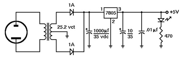
The completed power supply unit will look like the following picture (Pymm, 2006).
Requirements
- Power strip- this power strip will have the on/off switch and a circuit breaker that will protect the device from a power surge.
- Single Cord line which is appropriate for the power housing.
- Single transformer – This transformer will have; 25 Volts AC, 1.5 A. Proper matching with the line on an approximate voltage of 120V-240V (must work in both digital and analog power lines).
- About 6 wires nuts-Available in local hardware stores or home depot.
- Single 470Ω resistor (Yellow-violet and brown).
- Single 0.01 µf ceramic made capacitor.
- Single 10 µf, 35V capacitor made of electrolytic.
- Single 1000 µf, 35V capacitor made of electrolytic.
- 2 diodes for wave rectification with 25 diode rectification.
- 7805+5 IC voltage.
- 1 LED green in color.
- Wire assorted in many colors.
Tools necessary
There are several tools that will be necessary for the construction of a power supply. These tools include; longnose pliers, wire strippers, and diagonal cutters. A voltmeter will also be required to test the completed power supply designed and assembled.
Schematics
The designing platform of the power supply will be as follows:
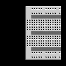
Breadboard for connection of the components:
Assembling the components
After acquiring the necessary requirements and tools to be used in the process, it is now time to join them in the breadboard that is shown above. Initially, it will be necessary to ensure that the jumpers are short enough and connected over the breadboard by the guidance of the schematic above.
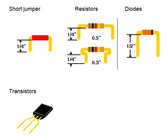
When assembling resistors, diodes, and capacitors, it would be important not to connect the components directly into the breadboard by bending their leads. These components can easily break under tension and thus destroying the usefulness of the component. On the other hand, diodes require different treatment; rectifier diodes normally dissipate a considerable amount of heat. Diodes used for signals usually have a glass body and thus require gentle handling. It is therefore required to cut the leads of the diodes ½ instead of the normal ¼ to space them on the board. Resistors should not be clipped because they are already short. The following figures should provide the basis of a correct way to clip the components:
The 7805+5 IC voltage should be placed in the center of the breadboard with the ground terminals and a source of power connected to the right terminal in order to ensure that the device works. The light-emitting diode should be placed next to the output of the +5V and also grounded. It is important to ensure that all the components are grounded in order to ensure that they function well. An external source of power is necessary and thus two pairs of wires should be used to connect to this source of power. Once the circuit is fixed in the breadboard, it will be necessary to taste its functionality before covering it with a protected insulator which will be its external covering.
Testing the constructed power supply
To ensure safety of the procedure, plugging in a power strip that essentially includes a switch and a circuit breaker to avoid overloading the device is necessary. This protection also protects the household against short circuits as a result of poor wiring.
The voltmeter should be set to a range of 0-20 volts and properly connected to the ground with a negative lead of the 1000 µf capacitor. After a proper connection is done, the lead input can thereafter be connected to the circuit board and the voltmeter turned on. Once the power switch is turned on, the green LED should consequently turn on. The readings of the voltmeter should subsequently read approximate of +4.75 V and +5.25. If there are any other voltages apart from the ones mentioned, then there is a possibility of wrong connections in the circuit that should be adjusted. Once rechecked, the 1000 µf capacitor should be connected to the positive lead of the voltmeter. The measurements of the voltage should be +17 volts or something close to this figure depending on the exact voltage of the line considering its tolerance.
Discussion
The 7805 IC voltage is the regulator and the heart of the circuit; this is basically because the IC provides a stable power output of +5 volts required for this designed power supply. The output of the power supply varied with a margin of about 5% which is still in an acceptable range. The green LED provided the necessary pilot signal to inform when the circuit system is on and when it is also off. More so, since the LED took some time to turn off after the power had been turned off because of the 1000 µf capacitor. The capacitor can store charge for some time after the power has been turned off. This capacitor is thus responsible for the regular function of the component given the 17 volts measured from this capacitor. Another major function of the LED in the circuit is to provide the necessary minimum required load on the equipment by providing the electrolyte capacitor a discharging point. As a result of these combinations, the portable or stand-alone power supply can hold power for a considerable amount of time, thus improving its efficiency.
Conclusion
As discussed in the theory design, the system designed as demonstrated above will be suitable for a computer system processing unit. The typical name for this kind of system is known as the switch mode power supply, this is the commonly used source of power supply in most computers especially the Pentium type of computers. As evident from the requirements of the design process, several components of the power system are dedicated to unique functions. The major components of the system include; power unit, power converter, power purification, and cooling unit. The power unit is responsible for the provision of the power from the mains, the power converter converts AC to DC, the power purification ensures a smooth sinusoidal curve of the power output. The last unit of the power supply is the cooling unit which is responsible for maintaining a constant temperature.
In the proposed design, several components have been used to create a portable power supply with an output of 5 volts. The major component is the 7805 IC which is responsible for the output of the 5 volts measured. The LED provides a discharge point and a signal about the status of the power on/off of the connected circuit. It is also important to note that the output of the designed system of power supply is subject to variation as a result of the component’s functionality and the total resistance of the circuit as a result of additional resistance by the jumpers and connecting wires. The variation is also caused by the tolerance of the components.
References
Gillespie, L. (2004). Designing electronic systems. Canberra: Wizard (Lyall Gillespie). pp. 1-4.
Malmstadt, E., & Crouch, J. (2004). Electronics and Instrumentation for Scientists. Canberra: The Benjamin/Cummings Publishing Company, Inc., pp.23-45.
Oklahoma,W. ( 2007). The Bargain Basement Power Supply Roundup, Canberra: Clareville Press. Web.
Pymm, Bob. (2006).”Building Collections for All Time: The Issue of Significance.” Australian Academic & Research Libraries. 37(1) (2006):61-73.
R. S. Khandpur. (2005).Printed circuit boards: design, fabrication, assembly and testing. Tata McGraw-Hill. p. 10. Web.
Wigmore, L. (2001). Electronics principles. Canberra:Dalton Publishing Company. Web.