Introduction
DC motors are machines that convert direct current electrical energy into mechanical energy or torque, whoch is also reffered to as the moment of a force. The operational mechanism of the motor is based on the forces that act on the magnetic field, which is caused by flow of direct current in a coil. Results show that the motion can be changed continuously by varyng the amount of current flowing in the circuit, which depends on the type of motor being used (Bose 2). Damodharan and Vasudevan note that DC motors have different characteristics because they are different from one another (3). It is important to note that the performance characteristics, which include the speed and torque output can be changed by changing the input current. In the experiment, an industrial machine was used to investigate the behavior of the motor in terms of speed and torque (Laskaris and Kladas 3). Figure 1 below shows the relationship between the applied force and the resulting torque on the winch.
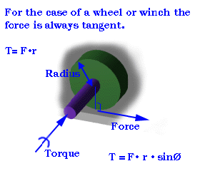
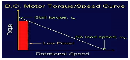
Figure 2 presents the characteristic curve that shows the theoretical relationship between speed and torque. Studies show that torque is always inversely proportional to speed. Increasing the speed reduces the torque and vice versa. The trade-off is a balance between how much speed is required for a given torque (Kang and Meneveau 5). Zulu, Mecrow and Armstrong argue that the output torque can be kept low by keeping the winch speed low. However, keeping the speed low increases the torque output from the motor (6). In that case, there is a strong relationship between torque and speed. Speed is measured in terms of the angular velocity (meter per second) while torque is measures in terms of newton per meter.
- Prot = Mechanical power due to rotation of winch (Watts)
- M = Torque Newton meters
- ω = Angular velocity (meters per second)
Maximum torque is said to be still when the shaft is not rotating and on the other hand, the speed can be
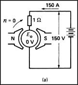
Figure 3 is an illustration of the effects of the magnetic field and the current on the rotating components of the DC motor and the output torque (Ozturk, Alexander and Toliyat 5). To find the relationship between torque and speed of the motor, an experiment was conducted in the laboratory using the following tools.
- DC power supply unit
- DC motor
- Clips
- Ammeter and Voltmeter
- Copper wires
- Hand Tachometer
- Electrodynamometer Module
Description
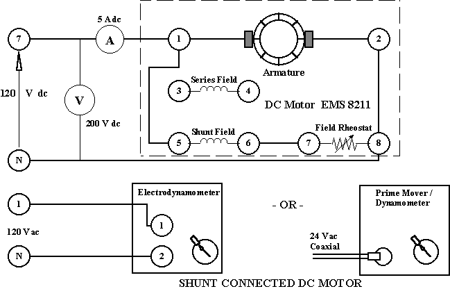
The circuit was set up as shown in figure 4 in a series motor circuit. The set up consisted of a motor and a shunt. The purpose of the shunt was to keep the speed of the DC motor constant when the flowing current caused a potential difference on the armature to prevent the loss in speed which happens due to the winding of the armature. It is important to note that the speed of the shunt motor can be made constant by keeping the armature winding as small as possible. The rating of each item should be noted and documented carefully.
Procedure
- Set the motor
- Shunt field rheostat control knob
- Set the brushes at a neutral position
- Ensure that the circuit is at a minimum load
- Rated current was allowed to flow through the winding of the motor by making the right adjustments in the circuit
- The speed of the motor could be varied by changing the characteristics of the load on the circuit.
- The armature current was rated by adjusting the generator field current
- The torque of the motor was varied by adjusting the load current on the generator from the lowest (zero) to the highest (maximum)
- A graph on the torque –speed relationship was drawn
- The experiment was repeated by changing the voltage to half its original value and noting the effects on the torque and the speed of the motor
Results
Table 1.
Table 1 shows the results that were obtained by conducting the three experiments. Results of the first experiment shows the impact of the input current on the speed. The same case applies to the second and third experiments. Each experiment used different current, voltage, and load characteristics. However, the first curve shows the speed and torque characteristics with the changes in voltage. Typically, the speed of the motor was controlled by adjusting the current supplied to the DC motor with the help of a shunt field rheostat. Here, because of the use of the shunt, the power loss is very small and the resulting effect on the motor is minimal
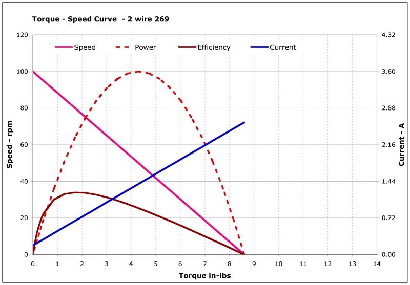
The speed of the DC motor changed with changes in speed. It is evident from figure 5 shows that when the speed reduces an increase in torque is observed and vice versa. It is worth noting that the maximum torque occurs when the speed is zero, when the winch is not rotating. However, to make the maximum use of the torque, it is important to adjust the speed to half its maximum value. That is the point at which the current is half its full value.
Conclusion
From the investigation that was done in the laboratory, it was possible to conclude that the maximum torque could be achieved by reducing the speed of the motor to half its original value. Values obtained were used to plot the curves showed that speed was directly proportional to the voltage, and the voltage due to the DC motor was inversely proportional to the torque.
Works Cited
Bose, Bimal K. Power electronics and motor drives: advances and trends. New York: Academic press, 2010. Print.
Damodharan, P., and Krishna Vasudevan. “Sensorless brushless DC motor drive based on the zero-crossing detection of back electromotive force (EMF) from the line voltage difference.” Energy Conversion, IEEE Transactions on 25.3 (2010): 661-668. Web.
Kang, Hyung Suk, and Charles Meneveau. “Direct mechanical torque sensor for model wind turbines.” Measurement Science and Technology 21.10 (2010): 105206. Print.
Laskaris, Konstantinos, and Antonios G. Kladas. “Internal permanent magnet motor design for electric vehicle drive.” Industrial Electronics, IEEE Transactions on 57.1 (2010): 138-145. Print.
Ozturk, Salih Baris, William C. Alexander, and Hamid Toliyat. “Direct torque control of four-switch brushless DC motor with non-sinusoidal back EMF.” Power Electronics, IEEE Transactions on 25.2 (2010): 263-271. Print
Zulu, Ackim, Barrie C. Mecrow, and Matthew Armstrong. “A wound-field three-phase flux-switching synchronous motor with all excitation sources on the stator.” Industry Applications, IEEE Transactions on 46.6 (2010): 2363-2371. Print.