Objectives
To investigate the relationship between the motor speeds, input voltage, and input current.
Apparatus
- U-154 Motor driver amplifier (10 Watts)
- U-155 Tacho amplifier unit
- U-156 DC power supply (±15V, 0.2A and motor power)
- U-157 Potentiometer
- U-159 Tachometer (FS 4000 RPM)
- U-161 Servo motor (Motor: 12V, 4.5W | Tacho generator: Approx. 3Vp-p/4000RPM)
- Multimeters
- Patch chords
Theoretical Background
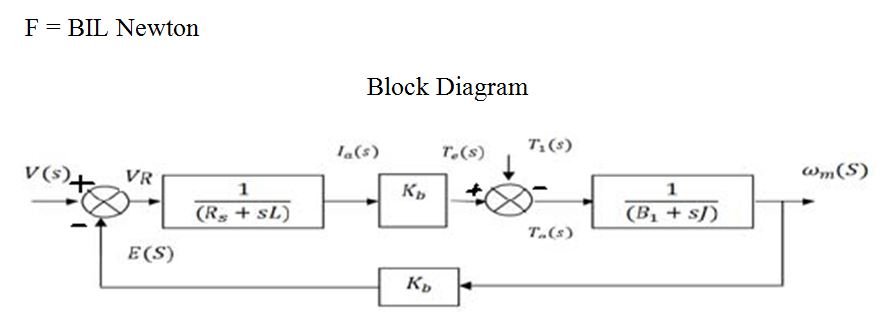
A DC motor is an electrical machine that converts electrical energy into mechanical energy. In a DC motor, the input electrical energy is the direct current, which is transformed into mechanical rotation. It works on the principle of Lorentz Law, which states that “the current-carrying conductor placed in a magnetic and electric field experiences a force” (Upadhyay et al., 2021, p. 341). And that force is the Lorentz force. A magnetic field arises in the air gap when the field coil of the DC motor is energized. The created magnetic field is in the direction of the radii of the armature. The magnetic field enters the armature from the North Pole side of the field coil and “exits” the armature from the field coil’s South Pole side. As such, when kept in a magnetic field, a current-carrying conductor gains torque and develops a tendency to move. In short, when electric fields and magnetic fields interact, a mechanical force arises. This is the principle on which the DC motors work. The direction of this force is given by Fleming’s left-hand rule and magnitude is given by;
Procedure
Referring to Fig. 2 above, the modules needed for the experiments were placed on the flat surface on top of the ED-4400b cover. The modules were then connected as indicated in the Fig. 2 above. Tacho-meter U-159 was then connected across the U-155 meter and the U-161. The angle on U-157 was then set at 1800. The line voltage was then verified to be corrected (220V). The U-156 line was then plugged into the power outlet, and the power was turned ON. The U-157 was turned slowly in a counter-clockwise direction until the motor began to move. The U-157 position and the input voltage were then recorded. Subsequently, the input voltage was increased slowly by turning the U-157 clockwise. In this case, for every on-volt increment of the input voltage (1V, 2V, 3V…) recorded, the U-159 indications were recorded with its subsequent current as indicated in the table below (see Table 1).
Measurements
Table 1: Table of input voltage (V), input current (mA) and RPM
Graphs
Summary
The speed of a DC motor is directly proportional to the input voltage. The greater the output speed, the stronger the input voltage. The output speed is slower when the input voltage is small. Using a DC motor control unit, researchers can regulate the speed of the torque separately by altering the supply voltage. Moreover, the speed of a DC motor is not linearly related to the armature current. Therefore, when the dc motor’s speed increases, the armature current will drop, but not linearly.
The description of the modules used in this experiment
- Dual Attenuator: The module consists of a dual rotary potentiometer which comprises of about 10 stages and each process is reduced to 10%. In this device, the total resistance is recorded as 100KOhm.
- Summing Amplifier: This comprises of a chain of inverting summing amplifiers. It is used to do the operations of tallying and assumes the role of the gain.
- Pre-amplifier: This component is intended to perform a DC Voltage offset. The choice of the set on the module is capable of potential +5 with a gain of 20Db.
- Motor driver amplifier: It serves as a protection circuit and also as a servo motor drive.
- Tacho Amp Unit: It is the unit that works to alter the output frequency become rpm tacho-generator.
- DC power supply: It serves to deliver a DC voltage supply device mounted to the +15V, 0.2A for the modules.
- Potentiometer: It comprises a precision potentiometer with a scale of 3600 swivel and is used to set and detect the position.
- Tachometer: The assessing device employed with AMP Tacho Unit used to the speed indicator derived from tacho generator output.
- DC servo motors: These encompasses a DC motor, gear speed reducer, and tacho generator for maximizing motor speed.
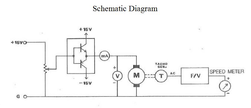
The schematic diagram explanation
A DC motor is a revolving mechanical device that transforms electrical energy into mechanical energy. It is centered on the force exerted on a conductor carrying a current inside a magnetic field (Wagenbach, 2022). When an electric charge is fed through the coil as seen in the figure, equal and opposing forces apply on the coil’s opposite arms, causing the coil to rotate (E-motors Direct, 2022). Brush contact keeps the spinning of the coil within the same orientation by inverting the direction of the current flow after each loop.
The graphs mentioned in the procedure and their relations
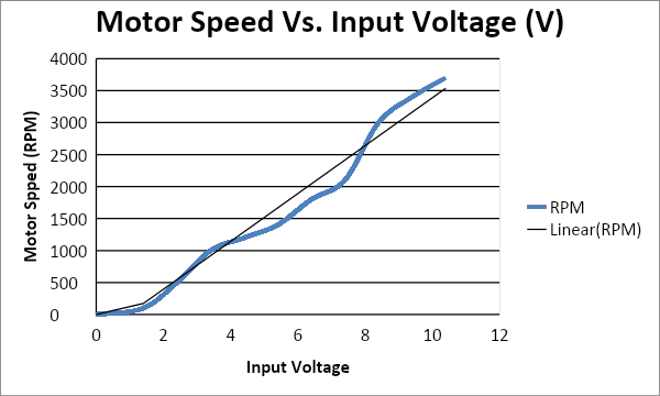
- Motor Speed Against Input Voltage: From the graph above (see Fig. 1), the motor speed is directly propositional to the input voltage. In this case, as the input voltage increases the motor speed also increases. However, the lower the input voltage, the slower the motor speed. Therefore, the speed of the motor can be controlled separately from the torque by altering the supply of the voltage at the DC motor control unit.
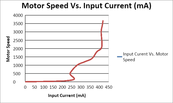
- Motor Speed against Input Current: The motor speed is not linearly proportional to the input current. Therefore, when the DC motor’s speed increases, the armature current does not drop with a unit amount; hence, it is not linear.
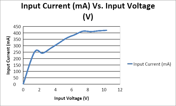
- From the graph (see Fig. 3), the motor current is not linearly proportional to the input voltage. At saturation, the motor input current no longer increases even if the input voltage is increased. As such, the effect of the saturation emanates from the counter electromotive force from the armature coil.
Reference List
DC motor RPM vs. Voltage: Relationship between motor speed and voltage (2022) Web.
Pilla, R. and Mehta, R. D (2022) Basic electrical engineering. New Delhi: S Chand Publishing.
Upadhyay, D. C. et al. (2021) Physics class XII Volume I. Agra, India: SBPD Publications.
Wagenbach, M (2022) Motor controllers: Input current versus Motor current, power conversion. Web.