Abstract
This experiment aims to discover and demonstrate a connection between the voltages across the resistor, capacitor, and inductor in an LCR circuit. We needed a capacitor, resistor, inductor, voltmeter, and power source. To acquire the voltage across the resistor (VR) and the voltage across the capacitor, we employed a constant capacitance value while changing the resistance in the circuit (VC). To examine and prove the relationship between the voltages, we utilized the formula V=V2c+V2r. The voltage from the power supply was 2.86v for the LCR circuit, and we received 2.84v after plugging in the other voltages into the calculation, giving us a percentage error of 0.70 percent.
Introduction
The primary goal of this experiment is to determine and verify the connection between the voltage all over the resistor, capacitor, and inductor in an LCR circuit. An LCR circuit also called an RLC circuit, is an electronic circuit that hosts a parallel or series connection of a capacitor (C), inductor (L), and resistor (R). In terms of phasors, the LCR circuit analysis may be better understood. A quantity that rotates through the circuit entails a phasor. For instance, if 1 is the reference axis then the voltage will lead by 90 degrees for the inductor while it will lag by 90 degrees for the capacitor (Pitchaimuthu & Kathamuthu, 2020). Conversely, the phasors of voltage, current and resistance always lie in phase. This experiment will demonstrate the relationship between an inductor, voltmeter, and resistor in an LCR circuit.
Materials and Methods
Materials
- Power source
- Capacitor
- BNC connector
- Crocodile clip
- Resistor
- Inductor
- Voltmeter
Methods
Voltage across the inductor, resistor and the capacitor were measured using a voltmeter. The value obtained from the three measurements was then compared with that acquired using the formula, (VL-Vc)2+(VR+Vr)2). Comparing the measured value with the calculated values is essential to determine the degree of error that this experiment holds.
Procedure
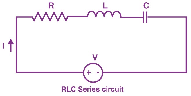
We had to be confident we had all of the essential equipment first, then we built and connected our LCR circuit using the LCR circuit schematic from our lab book. We took sure to measure our inductor first, then used a crocodile clip to attach it to the circuit. We set the frequency in the course to 100Hz and the capacitance to 1F after connecting it. We used the voltmeter to measure the amount of voltage produced by the power source once it was switched on. We next set our resistance box to 300 and measured the voltage in the resistor and capacitor with the voltmeter. The following diagram demonstrates the arrangement we used to determine the relationship between the three components of the LCR.
Results
The type of interaction between the voltages across the resistor, capacitor, and inductor in an LCR circuit is shown in the following tables. With a percentage error of just 0.70 percent, the voltage we obtained from the power supply is nearly identical to the voltage we acquired using this formula (VL-Vc)2+(VR+Vr)2).
Conclusion
The relationship between the voltage that passed across the capacitor, inductor, and resistor was obtained by the arrangement of the above experiment. Additionally, this voltage was in-line with that obtained when the standard formula for calculating voltage in an LCR circuit was applied. Notably, the above investigation was conducted when the inductor, capacitor, and resistor were arranged in a series circuit.
Reference
Pitchaimuthu, M. E., & Kathamuthu, T. (2020). Dynamics of the forced negative conductance series LCR circuit. International Journal of Circuit Theory and Applications, 48(2), 214-230.