Introduction
The academic study of the physical principles of electricity is not limited to the study of theoretical concepts but instead focuses on the possibilities of their practical application. In this virtual laboratory work, knowledge of the theory of the connection of resistors in an electrical circuit was tested: series and parallel. It seems quite evident that the differentiation in the two connections is based on the physical differences in the processes that take place. In fact, between the series and parallel connection of resistors in a circuit, there are differences in the total voltage and magnitude of the current flowing, which can be expressed formulaically as follows:
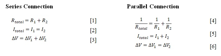
It is fair to admit that the third type of connection can be a mixed connection, consisting of a combination of the previous two, but it is not the task of this lab report to isolate this connection separately. In the case of a series connection, the resistors carry a common current, which means that there is only one path of electrons in the circuit, regardless of the number of resistors. In contrast, when the parts are combined in parallel, each of the resistors carries a unique current and increasing the number of resistors connected leads to a natural increase in the paths of current flow. In this regard, one can conclude that as the number of resistors connected in parallel increases, the total resistance decreases. Consequently, the total resistance will always be less than the resistance of any parallel-connected resistor.
It is reasonable to expect that when designing an electrical circuit with a particular type of connection, these laws will be confirmed. As part of this virtual laboratory work, two electrical circuits were created for which voltage and current values were measured at given resistances of three resistors and a power supply. The control tool for the report was a comparison of the measured and calculated values, and the measure of the reliability of the virtual experiment was the percentage difference between them. Thus, this report is useful academic material testing the laws of series and parallel connection of three resistors in electrical circuits.
Procedure
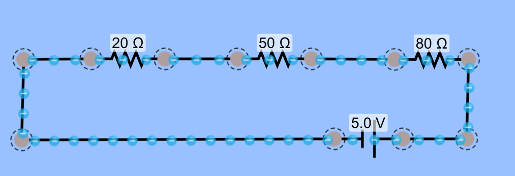
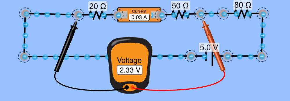
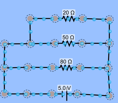
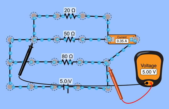
The interactive design environment PHET Colorado was used to conduct the virtual experiment, allowing for the design of electrical circuits and measurements. A circuit with a series connection of three resistors with specified resistance values and a power supply was created from a sample, as shown in Figure 1. For this circuit, voltage values were measured with a voltmeter, as shown in Figure 2. Furthermore, measurements were made for each of the resistors as well as for the combined connections. All values were recorded in Table 1. In addition, the values of the measured current with an ammeter were placed in the Table. For the parallel connection of three resistors with unchanged resistance values (Figure 3), similar measurements were made, and all values were recorded in the summary Table 1. Then, the design and measurement phase was replaced by the calculation phase, in which, using the mathematical expression of Ohm’s law — the Equation [7] — the current for each of the resistors and their combinations was calculated. The final step was to calculate the percentage difference between the measured and calculated current values.
I = U/R
Data Observations
Table 1.
Data Analysis
Analysis of Table 1 shows that there is no significant difference between the measured and calculated current values. Consequently, this Table perfectly confirms the truthfulness of the electrophysical laws of resistor connection. For greater accuracy, it should be noted how the calculations for the “Measured Current” columns in this Table were performed. For this purpose, a notation of Ohm’s law was used, stating that it is necessary to divide the voltage by resistance in order to calculate the current. As can be seen from the section for series connection, the voltage on each resistor was not the same; nevertheless, the calculated current was equal for all parts and also for their aggregate. At the same time, the voltages of the resistors connected in parallel were identical, so the calculated current for each resistor was unequal. To check the reliability of the obtained data, it was used the formula for calculating the percentage error specified in [8].
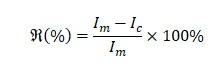
Since for each of the ten measurements, the percentage error was strictly equal to zero, one can assert high reliability of the data obtained.
Conclusion
In conclusion, it should be noted that the practical implementation of the studied electrophysical concepts is crucial to the successful mastery of the material. In this laboratory work, the laws of connecting resistors in an electrical circuit were studied: series and parallel. It was shown that there are unique patterns for each type of connection. In particular, a series connection of resistors looks at a common current, which means that the data from the ammeter should show identical numbers for each of the resistors. In contrast, the ammeter will show different data for a parallel connection because each part carries an individual current. It was also shown that Ohm’s law is satisfied for both types of connection. The calculated percentage error was zero in all ten measurements, which means that the experiment was highly reliable and reproducible.
Reference
Circuit construction kit. (n.d.). PHET Colorado. Web.