Introduction
Drive by wire is a new technology that has found its place in the modern automobile industry. It is a system which actively interprets the driver’s input and executes the commands to produce the desired vehicle behaviour by use of microprocessor-based control system (Guo, 2009). Guo (2009) also asserts that, “a common drive-by-wire system is made up of redundant sensors, actuators, microprocessors and communication channels for fault tolerance”.
There are no hydraulic and mechanical connections between the driver’s input interface e.g. through throttle, brake, steering and the vehicle system (Guo, 2009).
In a steer by wire system there is an increase in passive safety/crash performance such as no intrusion, and airbag position (Emadi Ehsani & Miller, 2003). It creates production benefits due to ability to easily convert left and right hand vehicle steering (Emadi Ehsani & Miller, 2003). This system drastically decreases the amount of energy that is consumed and prevents the unintended feedback/road disturbances to the driver.
How Steer By Wire Systems Works
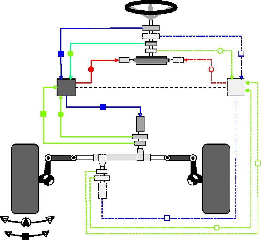
The steer by wire system also known as Electric power steering works with the help of an Electric Motor and a control unit which has some sensors. The system is powered by an electric supply from the battery and uses electric power to assist the movement of steering when the driver turns the wheel. The system is a component of the drive by wire technology uses microcontrollers to actuate the road wheels in the lateral direction based on the hand wheel steering angle and vehicle speed information (Guo, 2009). In steer by wire systems the hand wheel steering angle is measured via an appropriate sensor which is then communicated to two microcontrollers, these microcontrollers also receive vehicle speed information from the vehicle communication bus (Guo, 2009).
Based on the steering wheel angle and vehicle speed information, the microcontrollers calculate the road wheel angle command via suitable algorithms (Rajamani, 2011). The microcontroller then tries to sustain the commanded road wheel angle by actuating the rack mounted motors in a closed loop fashion through the road wheel angle feedback.
In the steer by wire system there are no mechanical coupling between the steering wheel and the steering mechanism which implies that the vehicle’s steering wheel is detached from the steering mechanism during normal operation (Ackermann, 2004). Even though the mechanical linkage between the steering wheel and the road wheels has been eliminated, a steer by the wire system is expected not only to implement the same functions as the traditional mechanically linked steering system, but also to provide the advanced steering functions (Rajamani, 2011).
Rajamani (2011, p. 22) indicates that, there are a number of important steering functional requirements necessary for the proper functioning of the steer-by-wire system, which includes:
- Adjustable steering feel
- Directional control and wheel synchronization
- Variable steering ratio
- Variable end travel stop for steering wheel
- Adjustable steering wheel returns capability
It can be noted that all the above mentioned components of the steer-by-wire system all comprise of multiple redundancy in the sensors, actuators, microcontrollers and communication buses (Ackermann, Guldner, Sienel, Steinhauser, & Utkin, 2005). This is obviously this way because of the design which ensures that any fault does not affect the vehicle so as to enhance the safety of the users (Rajamani, 2011).
Components of a Steer by Wire System
The steer-by-wire system modifies the driver’s steering command so as to ensure that ‘skidding’ is prevented (Rajamani, 2011). This is done in a way that ensures that there is no interference with the vehicle’s response in following the path desired by the driver (Rajamani, 2011). The figure below shows the structure of steer-by-wire stability control system.
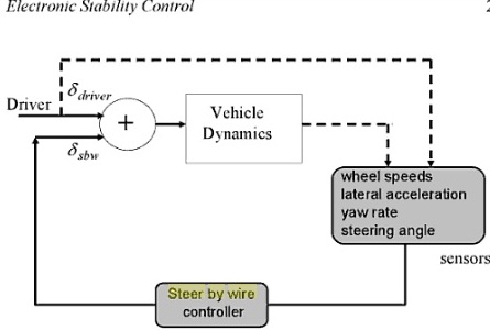
When the vehicle is running and then the driver applies a torque on the steering wheel which is connected to a one way working gear which can be easily be moved by the driver. The torque applied by the driver is transmitted in form of voltage to the steer by wire controller to the processor and the processor sends the output to an electrical motor (Wang, 2007). The voltage which is applied to the motor leads to a torque being applied to the steering gear (Wang, 2007).
The fine tuning of the functioning of the motor is achieved by having torque sensor in order to achieve the target torque (Wang, 2007). Acceleration and speed of the controlled wheels begin to move and the movement is determined by the resulting torques and the motor sustains the torque (Wang, 2007).
Electrical Supply in the Steer by Wire System
In order to power a steer by wire system an electric supply of 42V which originates from the batteries is used (Bolognesi, Bruno, Landi, Sani, Taponecco, 2003). The electrical system contains an additional element which is used to diagnose the charging condition and the disconnection of batteries (Bolognesi, Bruno, Landi, Sani, Taponecco, 2003).
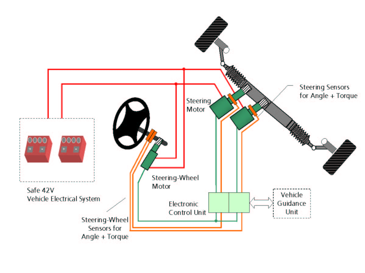
In this system, power stage and power supply to run the steering wheel motor are redundant and so in order to input a force on the steering wheel in case of a faulty steering motor, a torsion spring is attached which generates a return torque (Bolognesi, Bruno, Landi, Sani, Taponecco, 2003). An additional steering wheel motor can also be utilised in this system to generate the return torque (Bolognesi, Bruno, Landi, Sani, Taponecco, 2003). Attached to the vehicle wheel system is a set of redundant sensors and electric motors which are used to measure the torques and angles of vehicle manoeuvre (Bolognesi, Bruno, Landi, Sani, Taponecco, 2003). The steer by wire electronic control unit is fixed with fail-safe mechanism which has a signal processing, redundant power supply and power actuation (Bolognesi, Bruno, Landi, Sani, Taponecco, 2003).
HAZOP for Steer by Wire System
Up to the moment no verification method for absolute correctness of code exists and mistakes in design can be identified (Knowles, 2011). In order to carry out HAZOP analysis for steer by wire system, Failure Modes and Effects tests (FMEA) is employed. This is a classical system safety analysis technique which is currently widely used in the automotive, aerospace and other safety critical industries (Knowles, 2011).
Knowles (2011) asserts that,” In the Failure Modes and Effects tests, components failure modes are compiled and listed in order to try to understand the effects of the failure modes on the system”. In order to carry out these tests, analysts usually use simple diagrams to help them get to understand how the failure of steer by wire system might arise and cause hazardous effects to the user and to the vehicle (Knowles, 2011).
Unlike the bottom-up method FMEA, top-down methods break the system down in its components. Such methods in analysing failures are the event tree analysis (ETA) and fault tree analysis (FTA), which decompose system level failures in combinations of lower level events (Knowles, 2011). These are visualised in logical diagrams.
FMEA tabular method and the graphical FTA in bouncing failure analysis (BFA) are used to make the output of these two analyses available in one analysing process. Further used methods for analysing failures and their effects on reliability are hazard analysis and risk classification illustrated below.
In carrying out a hazard analysis of the steer by the wire, it is important to first consider the difference between feed forward and feedback systems on the level of the vehicle in case of a hazard. Steering ratio and stabilization are the two entities which are investigated in order to conduct the analysis and in both cases, as illustrated in the table below, the vehicle behaviour for the selected guidewords is explored.
Table 1: HAZOP for Variable Steering Ratio (VSR) and Yaw Rate Control (YRC) or the Steer by the Wire System
Findings from the above HAZOP analysis indicate that, in the “no” case, there seems to be a design implication on the variable steering ratio function, but not for the yaw rate control (Reinelt &Lundquist, 2006). While for the variable steering ratio functions all comments include driving situation and amplitude, only amplitude is mentioned in the yaw rate control case (Reinelt &Lundquist, 2006). This is due to the fact that the yaw rate control commands an action (unequal to zero) when an unstable driving situation occurs (Reinelt &Lundquist, 2006). In contrast, variable steering ratio function is always active and consequences of the hazard depend on the very situation as well (city traffic, motorway etc) (Reinelt &Lundquist, 2006).
Steer-by-Wire System Safety Components
One of the outstanding drawbacks of the steer-by-wire system is that any system that uses software possesses the ability to fail in spite of how the number of times the software has been put to test. Sensors in the system could make an error in calculation, which might lead to a malfunctioning of the system. This can lead to fatal accidents, even when the drivers think that they have the state of the art technology to insure their safety.
In many cases, people say that, “software is only as good as the programmers and manufacturers who built and designed it”. The truth is that the sensors in this system can fail and this makes the driving experience wildly fluctuating.
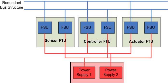
Steer-by-wire systems can be either fail-safe or fault-tolerant. Fail-safe systems have an independent mechanical backup system. The electronic control in such systems can take the form of a fail silent unit (FSU). In other words, system safety is sufficiently guaranteed if the electronics have a fault recognition mechanism that reliably ensures automatic shutdown when a fault occurs.
In order to address the above mentioned technical faults, engineers have put in place Fail-safe systems which have an independent mechanical backup system (Wang, 2007). The electronic control in this systems take the form of a fail silent unit which means that system safety is sufficiently guaranteed (Wang, 2007). In that whenever the electronics malfunctions, the fault recognition mechanism reliably ensures automatic shutdown when this happens (Wang, 2007). The fault-tolerant system which is also a safety mechanism in the Steer-by-wire systems, distributes the hardware across several redundant subsystems to ensure that system functions are maintained in their normal state (Wang, 2007). The subsystems have their own electronic control units and are networked via a fault-tolerant data bus (Wang, 2007).
Conclusion
Steer-by-wire systems are not available in automotive showrooms at present, but they may be available in times to come (Knowles, 2011). This system might offer many possible advantages such as active steering control, improved vehicle manoeuvrability, and steering systems tuning to a specific tuning to specific types of driving conditions (Knowles, 2011). However, before this system is commercialized, concerns regarding reliability and conformity of advantages must be completely satisfied (Knowles, 2011).
Bibliography
- Ackermann, J 2004, “Robust Decoupling, Ideal Steering Dynamics, and Yaw Stabilization of 4WS Cars,” Automatica, Vol.30, pp.1761-1768.
- Ackermann, J Guldner, J Sienel, W Steinhauser, R and Utkin, B 2005, “Linear and linear controller design for robust automatic steering”, IEEE transactions on control systems technology, Vol.3, No.1, pp. 132-142.
- Emadi, A Ehsani, M and Miller, JM 2003, Vehicular electric power systems: land, sea, air, and space vehicles, CRC Press, New York.
- Guo, H 2009, Automotive informatics and communicative systems: principles in vehicular networks and data exchange, Information Science Reference, Hershey, PA.
- Knowles, D 2011, Automotive suspension & steering system, Cengage Learning, Clifton Park, New York.
- Rajamani, R 2011, Vehicle Dynamics and Control, 2nd edition, Springer, Minneapolis, USA.
- Reinelt, W and Lundquist, C 2006, Controllability of active steering system hazards: From standards to driving tests, SAE International, Germany.
- Wang, LF 2007, Advanced motion control and sensing for intelligent vehicles, Springer, New York.