Introduction
Petroleum by-products are produced by organic compounds – living organisms that flourished in great numbers, died, decayed and were subjected to environmental pressures over eons. Some of these compounds are extremely simple; such as methane. Others have great structural complexity. Extracting all these has required equally complex processes of scientific exploration not two centuries old. Given the resource requirements of modern industry and transportation, demand is well-nigh endless and exploration has therefore covered both the deep seas and the most inhospitable conditions on land.
Exploration
Hydrocarbon exploration and production takes place in many regions of the world. The companies performing this task have to consider many factors and perform a variety of tasks. First petroleum or an oil companies will explore and select a region of their interest. They then consider the economical, environmental, political, social and technical aspect of a region they need to perform the function. When this is done, the most important factor is explored and that is the technical characteristics and the challenges they have to hurdle during the process of exploration and production of hydrocarbons.
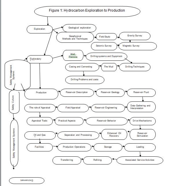
First of all the circumstances required for the continuous accretion of hydrocarbon deposits are scrutinized. Next the techniques used to find oil and gas deposits are monitored and defined.
Accumulation of Hydrocarbon
Hydrocarbons are formed and build up in the sedimentary basin which could be hundreds of kilometers in thickness. This is an area of sedimentary rocks. The formation of hydrocarbons take place in the pores of sedimentary rocks which becomes the source rock. Over millions of years organic remains from animals and dead plants are deposited continuously.
A high content of organic matter mounts up. This is continuously pressed by the overlying layers of humus and are buried deeper and deeper, thence exposed to elevated temperatures and pressures until they reach maturation, a condition when hydrocarbons are barred from their resource. Heat is the most important aspect which converts hydrocarbons into oil and gas. Heat increases with depth in the basin, and geothermal values range from 3°C – 42°C. Before maturation, hydrocarbons reside in impermeable spaces of the sedimentary rocks. After maturation hydrocarbons move to appropriate constitutions.
Migration
Migration of hydrocarbons occur in two phases. In first phase, they move towards the surface of the earth through minute fractures and pores of permeable rocks since hydrocarbon deposits are lighter in weight. In second stage, they have a propensity to move horizontally along the fault lines and flat surfaces of the rocks until settling into an appropriate reservoir. This is called a reservoir rock. Sometimes they percolate to the earth’s surface, in the process losing their explosive nature and coagulating as bitumen.
Methods and Techniques
Cost effective methods and techniques are developed to find new quantities of hydrocarbons. A field or seismic study is carried out on an extensive area to discover a prospective climax of hydrocarbons. This involves geophysical methods. Basic geophysical facts are explored in the surrounding geophysical structure. These methods include gravity, magnetic, seismic and electro magnetic surveys. In the end, only exploratory drilling can determine whether hydrocarbons are truly present in an area.
Geological Exploration
The general term for visual, mapping and other techniques (see following) for identifying subsurface structures with a high potential for containing hydrocarbon deposits.
Gravity Surveys
Gravity surveys are taken up in the beginning of an exploration endeavor. Spring balance is a measuring tool in gravity surveys which measures a wide range of values. Through this survey very minute deviations of the earth’s gravity field could be measured. Small changes in earth’s gravity field which root through density differences in geographical formation are identified by gravity surveys. The study of unreachable and larger areas has become more convenient due to airborne gravity technique.
Field Study
The comprehensive discipline and set of techniques aimed at assessing development opportunities in proven and potential oil fields. This helps prioritize future opportunities and optimize well completions.
Electromagnetic Surveys
Magnetic surveys are also carried out in the commencement of an exploration effort. Changes in the earth’s magnetic field are caused by deviations in the magnetic properties of rocks. This could be detected through magnetic surveys. The subterranean vault, igneous and sedimentary rocks are extremely magnetic. They give rise to irregularities with a petite wavelength and high amplitude when they are situated extremely close to the surface of the earth’s crust. These changes are identified by magnetic surveys. This is an airborne technique carried out with aircraft and allows quick assessments and plans with good exposure.
Seismic Surveys
Hydrocarbon basins are to be found thousands of meters underneath the earth’s surface; hence, their precise location and volume underground cannot be anticipated visually. Through seismic surveys, investigations are carried out to locate oil and gas reserves. In this survey, a two or three dimensional image of the subsoil surface of the earth presents information about the subsurface makeup. This is done by considering the prototype of dissemination of waves through earth. Sound waves are transmitted either at the surface (onshore) or under water and pass through into the earth’s subsurface. In this journey the sound waves go through reflection and refraction at a few geographical discontinuities. For example the periphery of a slanted fault block can present increased diffraction. Such objects can hamper the reading of seismic data which can either be detached or covered up during processing. The sound waves are reflected back at the interface between two rock units and are traced by the sensors. Some of the energy is bounced back to the surface and some of it is transmitted. As the wave passes through a rock, it changes its shape, the earth acts as a filter and modifies the waves. Such artifact can impede interpretation of the seismic data but can be removed or suppressed during processing.
Mirror image travel times are measured at different offsets and the disparity in travel times depends on the deepness, offset, and velocity to the reflector. For imaging the subsurface properly, data is collected from different offsets at different outlooks.
Seismic sources are of various types and these differ in the amount of energy released and the kind of frequencies generated. A thorough study of earth’s layers reveal that for a deep geological survey low frequency signals are needed, whereas for a shallow layer structure, a very high frequency signal is required.
For land surveys the archetypal sources are artificially generated with equipment mounted on truck or exploded in a superficial hole. The latter are masked explosives which are pierced into the ground.
When seismic waves move under the surface of the earth, they are reproduced back by a variety of rock layers. These are recognized and registered by seismic detectors which convert these waves into electrical pulse. These electrical outputs are augmented before they are recorded.
On land, the receivers which receive these reflections are called geophones. These receivers are prearranged over a wide area on the ground or in low boreholes.
In the sea, these receivers are called hydrophones and are arranged in arrays. Seismic surveys can be captured and processed by sensors arranged in straight lines, crisscross arrangements, a quadrangle loop and in a spherical pattern. Waves are initiated by condensed air guns which let off pulses of air into water. Hydrophones are either pulled following the container or are arranged out on the sea floor to receive the reflected waves. Borehole seismic surveys are carried out to detect the velocity differences between wells. These surveys produce a better image and have been proved to be extremely influential in field improvement and well development.
In seismic borehole surveys, the seismic source is located at the surface and the receiver is positioned in a bore hole. In case of borehole topography, both the source and the receiver are to be found in boreholes and the source is ablaze at different depths. Borehole seismic techniques give better motions and the capability to forecast and more precisely form the velocity differences linking the wells.
The surveying groups carrying out offshore surveys typically comprise two team members on board the journeying container. One member of the vessel carries out the navigation tasks while the other performs the seismic measurements. The waves for surveying are produced by compressed air guns which discharge pulsation of air into water. Hydrophones, enclosed in a streamer, are towed by the vessel to sense the reflected waves. All the reflections from various points are then stacked to provide one sketch for each common mid point. This leads to an improvement of the resolution of noise ratio signal.
Migration takes place in two steps: before stacking and after stacking. Before stacking migration or pre-stacking migration takes place before migrating the seismic data, while after stacking or post stacking migration takes place after the seismic data has been migrated. The later presents a good quality effect with smooth geological stratum and homogeneous seismic velocities. But when the seismic velocities differ to a minute extent or when the dips are minute, then pre-stacking provides a better result.
After migration comes the removal of multiples. These are signals that reflect at more than one point. A good example is a seabed multiple in many offshore seismic surveys. One of the strongest reflector is a sea surface. When waves travel upwards, they bounce off the surface of the sea before these are reflected for the second time at the seabed.
Geologists and geophysicists perform the interpretation of the seismic data after it has been loaded onto a powerful computer called a workstation.
Exploratory Drilling
Exploratory drilling has been carried out at least since the mid-19th century, when subsurface deposits were suspected in North America and the Middle East fields. Given that the environments vary from hills along fault lines to the depths of the North Sea, arid desserts and the Artic wastes of Siberia and the North Slope of Alaska, exploratory drilling requires extensive planning, an understanding of drilling systems equipment required in this process, techniques applied, drilling problems and costs.
Well Planning
Proper planning includes identification of sites, the assimilation of many regulatory techniques and assembling the necessary expertise. With successful well drilling information is gathered; hydrocarbons are produced; water and carbon dioxide is disposed of; and gas or water is injected force residual oil deposits upward.
Drilling Systems and Equipment
A drilling rig comprises four primary systems (“Types of Oil Drilling Rigs” 1):
- A hoisting or lifting component, also called the “derrick” or “drawworks”.
- A drive train – consisting of motors and chains – to rotate the drill.
- Circulation pumps, a kelly (a pipe square or hexagonal in cross-section for transferring rotary motion to both the drill string and turntable), drill string (the drill pipe itself, usually in 10-meter sections, plus the drill collars that fit around the string and bears its weight on the drill bit), return lines, and pits.
- Well control equipment.
The basic equipment is the rotary rig. The torque is transmitted form the power source at a surface through a drill string to the drill bit. A drilling fluid is pumped from a storage unit down the drill string and up through the annulus. The fluid brings the cuttings created by the bit action to the surface, hence cleaning the hole, cooling the bit and lubricating the bit string. The subsurface pressures are controlled by the weight of drilling fluid.
Rock bit and poly crystalline diamond compact bits are the commonly used drill types. Depending on the type of the well the rotary movement is generated mainly by three methods: the transmission of rotary motion by a pipe called Kelly generated at the surface by rotary table; by a power swivel connected directly to the last drill pipe; and by a drilling turbine or engine at the top of the well itself. Between the bit and the surface, where the torque is generated, we find the drill string. The drill collars are thick-walled, heavy lengths of pipe. They keep the drill string in tension and provide weight onto the bit. To increase, hold and decrease the hole angle, stabilizers are added to the drill string.
Wells are differentiated according to the purpose for which these are drilled. The “exploratory” wells are those used to ascertain the presence of a reservoir, whether insubstantial or commercial. If the reservoir is found to be commercially feasible, a higher-capacity “development well” is drilled. The term also applies to additional wells drilled in an area or field that is already proven. In this case, the intent is to maximize production in a field that is already proven.
Drilling Techniques
Rotary-type (also referred to as “conventional”) drilling is the most common. With the aid of the weight of the drill stem or casing, a rotating drill bit is impelled downward into the earth or sea bottom to make the hole or “wellbore”. Being connected to the drill bit, the drill stem provides the rotating action at the same time that it provides a channel through which drilling mud (or other fluid) is circulated to lessen the friction of the drill biting into bedrock.
On occasion, it is not possible to drill straight down. For instance, an ecologically-sensitive area may be right on top of the oil-bearing structure. In this case, the field team will drill vertically in an adjacent area and then make a sharp horizontal turn at some point perpendicular to the suspected or known reservoir. This process requires special drill bits since the well no longer has the weight of the stem to bear down and transfer rotational force.
Much the same principle applies to “slant” or “directional drilling” when the well is drilled at an angle. Again, this is done to protect a land area over which there are environmental concerns. The difference is that the rig in a less ecologically sensitive area can drill multiple angled holes may be drilled from one rig to maximize reservoir production.
As to ultra-modern techniques, Freudenrich (1) reports that the U.S. Department of Energy and oil exploration companies industry are already testing the use of lasers to bore wells. This is presumably applicable to the permafrost that covers the North Slope fields in Alaska.
Other drilling techniques have to do with extracting shale oil or small pockets of crude from largely depleted fields. In the former, oil is mixed with sedimentary layers while the residual crude in “exhausted fields” exists in such small quantities that there is no pressure that readily forces it to the surface. In this case, two wellbores are drilled, one over the other and in fairly close proximity. Steam, gas or water is injected from into the overhead hole in order to force oil down into the other bore hole and and thereby facilitate extraction.
The Mud
Mud is disseminated in the well during drilling. This is to ensure that the bottom of the well is properly cleaned out, the drilling bit is cooled and lubricated, the walls of the well-bore are well consolidated, and the pressure is put into effect to control the flow of oil or gas.
Casing and Cementing
The casing is a large-diameter concrete pipe lining the well. This is necessary to stop the hole from caving in and it is another channel for drilling mud to circulate upward or downward.
The casing is done when the hole reaches its pre-determined depth. This step is called “running and cementing the casing”. As the drill bit progresses downward, sections of casing pipe are rammed into the well to forestall the hole collapsing in on itself. On the exterior of the casing pipe are “spacers” that keep the it centered within the hole. After setting a bottom plug in place, the cement crew pumps cement slurry down the casing pipe followed by a top plug and drill mud. The weight of the drill mud causes the cement slurry to flow down the casing, filling the space between the casing exterior and the hole. After the cement hardens, it is tested for such hardness, alignment and a proper seal.
Drilling Problems and Costs
Beyond the problems attendant to the location of the field – the depths of the North Sea, unrest in the Middle East or drilling through Artic permafrost that stays hard even in the summer, the more frequently-occurring problems have to do with accidents that impede drilling and raise operating cost.
The most common type of problem is when some piece of metal or other hard object breaks off and drops to the bottom of the well. A segment of the drillpipe may twist off (owing to the constant rotational stress) and fall down the well or one of the three cones in the tricone drill bit gets detached. Both pieces of “debris” are metal and, the composite-diamond construction of a drillbit notwithstanding, attempting to drill through is either impossible or will hasten the wearing out of the bit. Drilling is suspended and a special piece of equipment called the “fishing tool” must be leased from a service provider to get rid of the “junk” or “fish”. Essentially, the fishing tool is lowered down the well to grapple blindly for the “fish”, hence the term. Since this arduous process can last many days during which contract per-day drilling costs continue to apply, exploration companies compensate by buying fishing insurance before drilling commences.
Another problem that adds to drilling cost is “lost circulation”. When the well moves past a very permeable formation, the follow-on operation of sending drilling mud down the casing and back up between the surrounding rock is stymied by the fact that the drilling mud is absorbed by the highly-permeable zone (hence the term “lost circulation zone”) and the filter cake along the wellbore does not form. “Lost circulation is detected when very little, if any drilling mud returns to the surface. This is a significant resource loss since “drilling mud” is a synthetic compound commonly consisting of bentonite clay (gel), additives like barium sulfate (barite), calcium carbonate (chalk) or hematite. Other components raise fluid viscosity – these are the thickeners Xanthan gum, guar gum, glycol, carboxymethylcellulose, polyanionic cellulose (PAC), or starch – while making a more dilute mixture depends on deflocculants (anionic polyelectrolytes like acrylates, polyphosphates, lignosulfonates (Lig) or tannic acid derivates such as Quebracho). So, lost circulation throws away a component of variable cost. Secondly, drilling companies keep overhead down by purchasing and storing only a finite amount of drilling mud near the well. Again, drilling must stop until newly-acquired supplies of finegrained, fibrous particles called “lost circulation material” can be pumped down the well to plug the lost circulation zone.
But potentially the most serious problem is “kick”, which occurs when drilling hits an area of abnormally high pressure. The drill bit encounters a rock layer where the water, gas or oil pressure in the pores of the rock is much greater than anticipated. The pressure exerted by drilling mud alone cannot control it and the now-released fluids flow into the well and upward since these have nowhere else to go. Warning is provided by pressure sensors and by the fact that the drilling mud starts to flowing back out of the top of the well at a very high rate. The solution is to “kill” the well by closing the blowout preventer and subsequently pumping very heavy drilling mud (“kill mud”) down the well to bring the disruptive pressure under control. Drilling continues with kill mud in place of ordinary drilling mud this time. The worst-case is when the well is not killed in time and the backpressure is caused by natural gas. When this flows to the surface and catches fire during a blowout, both the rig and drilling equipment are destroyed (Hyne, p. 1).
Non-disrupted Drilling Costs
The cost of a new well is determined chiefly by the depth to which exploratory work suggests it should be drilled. Accordingly, drilling contractors charge per day it will take to reach the specified depth or X dollars per foot of depth (PetroStrategies, p. 1).
Table 1: Costs of Crude Oil and Natural Gas Wells Drilled. Source: Energy Information Administration (2008)
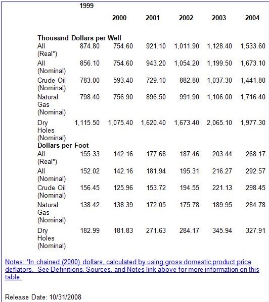
As of 2004, the survey of domestic industry drilling costs by the U.S. Department of Energy’s Energy Information Administration (EIA) showed that it cost $1.4 million to drill an oil well and $1.7 million for a natural gas well (Table 1 above). Worth noting is the fact that drilling a dry hole still happens despite advances in sensing and exploration technology; for “mistakes” such as this, the sunk cost can average $1.98 million.
The average cost to drill a well was $297/foot of depth. This time, crude oil wells cost somewhat more ($298.45 per foot) than gas wells do ($285 per foot).
Even after adjusting for inflation (using the more general GDP deflator rather than the more publicized (but inapplicable) consumer price index, it is clear that drilling costs continue to rise, doubling in fact within a span of five years.
Production
Commencing from when oil or natural gas is determined to exist in commercial quantities in a well or entire field, all the activities that have to do with extraction.
Reservoir Description
Since “reservoir” refers to the subsurface, porous, permeable rock structure or formation in which oil and gas are found, reservoir description refers to all the services, activities, and products that characterize the reservoir rock and reservoir fluids. This itself involves a diverse set of activities that include sampling and analysis of reservoir fluid, basic and advanced rock properties and rheological analysis (the study of the flow of liquids and even “solids” that flow under pressure) of drilling fluids and cements. Essentially, reservoir description characterizes the phase behavior and other properties, of crude oils, natural gases, and other reservoir fluids in order to optimize production of a field or well.
One example of reservoir description tools are microprocessor-equipped probes sent down a well to profile formation fluid and other reservoir data: horizontal mobility, anisotropy, resistivity/capacitance, viscosity, density, bubble point, compressibility, horizontal and vertical permeability, and anisotropy.
Reservoir Geology
This branch of geology is concerned with analysis in respect of field delineation, defining field structure, the petrophysical properties of subsurface reservoirs, evaluations of field resources and hydrocarbon migration. Typically, drill samples, seismic surveys, petrophysical logs and fault or fracture patterns on the surface are analyzed to assess the limits and potential of a geological formation as to porosity and hydrocarbon saturation, deposit characteristics and even fluid migration routes.
Field Appraisal
Once exploratory drilling has established the presence of a reservoir of sizeable size, field appraisal immediately follows. At the very least, this calls for delineation wells to be drilled so as to determine the extent of the oil or gas field and how it could be developed in the most productive manner.
To an extent, field appraisal overlaps with characterization in that utmost efforts must be exerted to assess the commercial potential of a discovered field. To reduce uncertainty, exploratory companies may resort to computerized modeling of seismic survey results, taking as inputs geological descriptions and engineering design parameter uncertainties with the intent of modeling a full range from delivery to reservoir simulation and production.
Reservoir Fluids
Essentially, the study of reservoir fluids involve measuring and predicting the thermodynamic behavior of oil and gas reservoir fluids so as to maximize the development of a new field, design and selection of transmission and processing facilities, and testing the cost-effectiveness of alternative recovery techniques. Instruments and facilities to test pressure, volume, and temperature are deployed in order to assess various production scenarios.
Data-Gathering and Interpretation
Sensor information about the characteristics of reservoir fluids is organized, stored and retrieved. These include fluid data such as PVT, geochemistry, flow assurance, enhanced oil recovery, oilfield water chemistry and refinery/assay data. Among others, thermodynamic models and equations of state are developed to predict fluid properties at all production stages and scenarios:
- Fluid composition, viscosity, density, interfacial tension, characterization and saturation point.
- Depletion when subjected to ordinary PVT tests;
- Gas Injection, backward and forward contact, and Swelling test;
- Minimum Miscibility Pressure and Enrichment
- Simulation of gas inflow and pressure build-up adjacent to the well bore;
- Gas Recycling of partly-depleted reservoirs
- When reservoir samples are inadvertently mixed with oil-based drilling mud
These tests extend to the phase behavior of gas condensate and volatile oils throughout the whole production process.
Production Costs
The EIA (2007) reports that the average cost to locate and develop oil and gas in the United States was $10.33/BOE (barrels of oil equivalent) from 2002-2004. Onshore development amounted to $7.18/BOE and offshore development ran nearly four times as much at $27.66/BOE.
Equipment, lease, development and production costs vary widely, again depending on the hydrocarbon obtained, location, depth, and whether the well is in its primary production state or already in enhanced-recovery operations.
Oil leases, for instance ran from a low of $918,700 for a shallow-depth (2,000 feet) 10-well field in Mid-continent up to $17.9 million for secondary recovery in the same-size field in West Texas but drilled down to a depth of 8,000 feet (EIA 2007).
Annual operating cost for the same 10-well oil field benchmark ranged from $186,400 at 2,000 feet in West Texas and three times as much when drilled down to 12,000 feet in California.
In the case of natural gas fields, equipment costs are more homogenous within depth and production rates. Two years ago, equipment costs for a 1-well gas lease producing 5 MMCF/D (million cubic feet per day) and found at a depth of 16,000 feet ranged narrowly from $112,500 in West Texas to just 115,300 in mid-continent. For the same benchmarks, annual operating costs stood at from $61,100 to $67,600. At the far richer North Louisiana field (10 MMCF/D) drilled down to the same depth, yearly operating costs were just one-third more at $88,100.
Storage, Loading and Transferring
Pipelines are virtually the universal way for transferring crude oil and gas from wellhead direct to refinery or through tanker ships and barges when the refinery is more distant or overseas.
Well Rehabilitation
This step is taken for two reasons. The first is when an industrial accident occurred. In the second case, a well that has been “depleted” may be rehabilitated with extraordinary rehabilitation methods when market prices make it economic once more to try and recover more petroleum.
In the most common field incident, the casing has broken and drilling mud entered the hole thus clogging the pump. Rehabilitation is a mechanical procedure where the well is re-entered and everything within the well bore is first extracted: the pump, rods, and tubing. All that is necessary then is to clean out the tubing of whatever drilling mud clogged the tubing above the pump. Subsequently, the tubing is run back in the hole and a swab test conducted to see what quantity of oil will flow and whether it will prove unadulterated. If test results prove favorable, the rods and pump are placed back in the well and it is restored to regular production. In the category of “acts of God and the common enemy,” there comes to mind the Iraqi sabotage of hundreds of oil wells during the 1991 invasion. Close to 2,000 wells that were on fire had to be extinguished by extraordinary means and then capped. Months of effort by dozens of teams were needed just to stanch the flow and start repairing the destruction to the wellheads.
Enhanced Well and Field Recovery
There are various methods for re-stimulating production from otherwise-moribund wells. One involves the fairly straightforward lowering of a gas gun with a deflector or an arc sparker into the oil well bore; activating the gas gun creates percussive waves that remove impediments such as stones or rock. Another fairly common rehabilitation problem is active water cresting, coning or under-running, collectively known as “water coning”. Gelation and the dual completion technique (otherwise known as the downhole water sink) are two techniques for attenuating the problem and delaying the onset of water contaminating oil brought to ground level.
Strenuous recovery efforts are being made partly because production has steadily declined in many oil-producing areas: inland wells in the United States, the Persian Gulf and the Norwegian Continental Shelf. As well, price volatility has frequently made the cost-benefit ratio of enhanced recovery decidedly positive.
In general, there are three recovery stages. Primary recovery is the easy stage when gravitational pull and the original pressure with the petroleum reservoir are quite enough to lift oil to the surface with some lift provided by pumps. But this typically lifts just 10% of the reservoir to the surface in inland U.S. wells (U. S. Dept. of Energy, 2008).
Hence, most producing fields proceed right away to secondary recovery techniques. The productive life of a field is extended, usually by pumping water or gas down so as to force oil toward the wellbore. These two methods can extract from 20 to 40 percent of the original reservoir.
At the tertiary stage, enhanced oil recovery (EOR) techniques are brought into play to raise productivity to 30 to 60 percent or even more of a reservoir’s content. Four broad EOR classes proven economical and mechanically useful, with the choice dependent on reservoir pressure and depth, temperature, rock permeability or porosity, marginal saturation of oil and water, and the API gravity and viscosity of the petroleum itself.
- Thermal recovery (also known as “steamflood”), the injection of heat (typically steam but slow combustion is also used) to reduce viscosity and improve flow through the reservoir toward the wellbore. Heat application accounts for fully half of EOR production in the U.S.A.
- Gas injection, typically employing natural or manmade carbon dioxide (CO2) but also extending to natural gas and nitrogen, accounts for most of the other half of EOR volumes. In the depths at which reservoirs are found, the combination of heat and pressure causes gases to expand and push additional oil to the wellbore. Other gases readily enter into a solution with petroleum and hence, improves flow rate.
- Chemical injection (also termed “alkaline flooding” or “micellar-polymer flooding”), employs either long-chained polymers to improve waterflooding success or surfactants that lower surface tension of oil droplets and helps them flow more easily through the reservoir. The sheer expense of such chemicals has limited their utility to less than 1% of U.S. EOR production, the Dept. of Energy (2008) reports.
It is not commonly acknowledged but EOR techniques are costly, are not always effective and, in the case of CO2 injection, a lethal addition to the “carbon footprint” of the entire petroleum industry.
Production and Refinery Operations
Owing to the separation of lighter distillates (e.g. LPG, kerosene, gasoline) from heavier components (fuel oil, diesel) during refining, the standard each barrel 42-U.S. gallons of crude converts to 44 gallons of oil products.
About half of each barrel of crude is refined into gasoline for cars and avgas for jetplanes. Nearly one-fourth is refined into diesel for marine and truck engines. The rest is turned into many other products.
Overview of Oil Refinery Operations
There are several kinds of refineries:
- Topping Refineries are the smallest and the simplest. At its most basic, these may have only an atmospheric distillation tower and perhaps a vacuum distillation tower. Lacking the more sophisticated refining equipment, toppine refineries are limited in what they can produce and are greatly affected by the quality of the crude oil received.
- Hydroskimming Refineries have desulfurization and reforming units, topping units. These can increase the octane levels of gasoline and lower the sulfur levels in diesel fuel.
- Complex Refineries are the largest and employ the most technologically advanced refining equipment and processes. Having the ability to “crack” (see below) the heavier or less desirable grades of oil, they are more productive in extracting higher-value, lighter petroleum products such as gasoline for cars. More important, refinery complexes can process every type of crude extracted in any field around the globe. Refining is a somewhat complicated and technical process. In the simplest terms, this is how oil is refined:
- Distillation (or separation). The hydrocarbons in crude oil are distilled in order to separate heavier components like asphalt or diesel fuel from the lighter distillates such as kerosene.
- Conversion (or cracking). Cracking towers break up (hence the term “cracked”) hydrocarbon molecules in a conversion process enabling the refinery to produce a proportionately more of the lighter, more valuable petroleum products in greater demand, gasoline being the prime example; and
- Treatment (or enhancement). Refineries can improve the petroleum products, such as gas, heating oil, and kerosene, by treating it to remove sulfur. The treatment stage may also entail the blending enhancers to gasoline so as to produce the by-now familiar grades of regular, unleaded and leaded premium gasoline.
Environment, Health and Safety Management
The industry is subject to a wide range of health, safety, environment and emission control laws and regulations owing to:
- The extreme flammability of its byproducts, the very reason why pipelines, refineries and storage depots must be situated far from urban centers and residential neighborhoods.
- The reckless spillage and inescapable evaporation of volatile gasoline and thinners when transferred from refinery tanks to loading tanker wagons thence to gas station talks and vehicle tanks. This raises concerns about greenhouse gases, harm to marine life and to the ozone layer.
- The risks refinery workers face from constant exposure to petroleum distillates and additives used in refining.
- And from end-users, the industrial effluents, heat output and combustion byproducts that befoul the environment.
Measures taken to comply with health and environmental issues have added to refinery costs. Recall that leaded gasoline used to very popular because its higher octane rating boosted the performance of car engines. When evidence about lead poisoning mounted, refineries switched to MTBE (methyl tertiary-butyl ether) which also reduced engine “knock” and, because it effectively oxygenated gasoline, made the fuel burn more cleanly and reduced emission of polluting compounds. Along with ethanol, increasing concentrations of MTBE have been used to comply with the oxygenate requirements of the 1990 Clean Air Act Amendments.
Other additives and processes have to do with reducing “greenhouse gas” (GHG) emissions, the most stringent of these around the nation being the one in California because of the deadly prevalence of ground-level ozone (“smog”) in the Los Angeles basin. At the cost of more expensive gasoline, the state banned leaded gasoline in 1992 and imposed extensive formula changes in 1996 to reduce smog-forming emissions from motor vehicles by 15 percent and draw down toxic air emissions from gasoline use by 40 percent. New regulations taking effect in 2003 banned MTBE and reduced the allowable amount of sulfur and benzene in gasoline. Even more recently, Gov. Schwarzenegger enacted the Low Carbon Fuel Standard (LCFS) requiring refiners to reduce GHG emissions (chiefly CO2) by 10% in their total fuel mix by 2020. The immediate impact of course is to increase usage of ethanol in the final gasoline blending done by refineries.
Works Cited
Energy Information Administration “Oil and Gas Lease Equipment and Operating Costs 1988 Through 2006.” 2007. Dept. of Energy.
Energy Information Administration “Costs of Crude Oil and Natural Gas Wells Drilled.” 2008. Crude reserves and Production.
Freudenrich, Craig C. “How Oil Drilling Works.” 2005. Energy Capital Group. Web.
Hyne, Norman J.“ Finding and Producing Oil and Gas.” 2000. Internet Oil and Gas Newsletter.
PetroStrategies Inc.“Drilling Costs.” 2007. Drilling Operations.
“Types of Oil Drilling Rigs.” 2008. JobMonkey.com.
U.S. Dept. of Energy “Enhanced Oil Recovery/CO2 Injection.” 2008. Web.