Aim
There have been many developments in the field of aviation ever since the introduction of aircrafts. Different techniques and aids are constantly being improved for the execution of safe and smooth landings so as to complete this trickiest phase of a flight with less difficulty and more perfection. The aim of this paper is to look into the characteristic features of various prominent precision approaches such as, Instrument Landing System (ILS), Microwave Landing System (MLS), Wide Area Augmentation System (WAAS) and Local Area Augmentation System (LAAS); their components, the principle of operation; their limitations and probability of improvements in future. It also focuses on the comprehensive study of the future precision approach system called Smart Path, a ground based augmentation system, developed by Honeywell, and selected by FAA as an upcoming replacement for ILS in its Next Gen program. This paper also evaluates the importance of these systems in providing safety and reducing operational expenditures of airlines. Hence, the aim of this paper is to analyze the adequacy and accuracy of the landing aids and their implementation with respect to their requirements and practicability in aviation at present and in the years to come.
Executive Summary
Landing is the most crucial and demanding phase of a flight. For a smooth and safe landing of an aircraft it is necessary that the pilot is assisted with some landing aids. There are several technological navigation aids that help in the execution of a precision approach and landing.
The ILS is a combination of both approach lighting and radio beacons including their best qualities within one system. Though it is an important landing aid providing the lateral and vertical guidance necessary for a precision approach but in view of the future aviation requirements, it has certain limitations which prohibit or restrict its use in many circumstances.
MLS offers many advantages over ILS besides overcoming its confines. Accurate precision navigation guidance is provided by this system relative to the alignment and landing of aircraft. It is appropriate for the autoland approaches where the aircraft is controlled by the equipment as it allows safer landings in extreme weather, with zero visibility.
Further, two augmentations systems are developed, known as LAAS and WAAS, to assist the GPS in the civil aviation with space based navigation. Global, standardized navigation services for all types of aircraft operations and all phases of flight can be made available with the use of differentially corrected GPS service, with the support of WAAS and the LAAS.
The requirement of GPS to get some assistance from the ground for rapid descending of an aircraft quite near to the ground paved the way for a ground based augmentation system (GBAS), which is also called Smart Path and is an effective system to smarten up air-traffic control. The replacement of ILS with GBAS technology has been recognized crucial for the enhancement of the air traffic capacity in the FAA’s Next Gen program and Euro control’s Single European Sky ATM Research Program. GBAS avionics have become an integral part of most current-production Airbus and Boeing aircraft. GBAS, described as SmartPath by Honeywell, is the initial stage of an infinite plan to refurbish air-traffic control.
The limitations of older technologies in ensuring safe landings where only short-length airstrips are available due to deserts or vegetated areas and in rough seas, led to the development of autoland system. Different climate and weather conditions affect the approach and landing phase of an aircraft considerably. Autoland systems are used to ensure a safe landing in extreme weather conditions and intense levels of visibility.
Advancements in avionics such as the SmartPath, introduced by Honeywell and the autoland system are not only cost effective but also suggest an increasing role for flight inspections chances, in the coming years, with respect to the navigation and landing aids.
Development in Aircraft Landing Technology
Introduction
Landings are the most crucial phase of a flight and carry significant safety messages with their execution. Missing of any essential correction and misjudgments at any point may result into an immense calamity. Most of the accidents are caused by inaccurate procedures in the landing phase (Horne 2011).
The complexities involved in the process generate chances of accidents taking place. So, in order to return the aircraft back to the earth safely and firmly, a skillful execution of the landing phase is highly required. It is essential to have an ideal knowledge of the various aspects such as: what should be the speed, knowledge regarding the rate of descent and glide path along with an absolute judgment of glide path (Nirjharini 2011).
To achieve a smooth and secure landing a number of technological navigation aids can be used by the pilot. Initially, there were only people-powered landing aids where people used to stand on the field with flags to provide direction to the aircraft. They used to wave red, green, or white cloths symbolizing different signals (Mola n.d.).
Gradually, the radio controllers were developed to provide some landing aid to the pilots. Moreover, red or green lights were also utilized to present the view of the runway threshold and sides in the airport. This helped the pilot to judge the remaining distance and angle to be taken for landing (Mola n.d.).
History
Development of aircrafts: Before the existence of airports and introduction of any landing aids, the pilots used to be guided by the direction of the wind, in landing the aircrafts. With the constant growth of air traffic, the airports were developed and landing was restricted to definite directions. The complexities faced during the landing of an aircraft were resolved to some extent with the development of the landing aids that enabled pilots to stick to a correct landing course, thus making it safer (Mola n.d.).
Use of lights: Airports began the use of lights in the late 1920s.Landing fields were marked with rotating lights that offered guidance to the pilots in the dark. The use of approach lighting in the airports in the early 1930s helped the pilots by guiding them to take proper descent and ensured that they were on the right direction. “The approach path was called the glide path or glideslope” (Mola n.d.). In course of time, the International Civil Aviation Organization (ICAO) provided a standardized form of the colors of the lights and their rates of flash to be recognized in all over the world (Molan.d.).
Introduction to slop-line approach: The slope-line approach was the first system implemented as landing aids that was a cone shaped formation of rows of lights (funnel) providing guidance to the pilot to reach the finishing point of the runway. In case of some deviation to the right or left, or too high or low other patterns of lights were exhibited. Although this system, developed in 1940’s was economical to build and operate but some constraints restricted it from being used in certain airports (Molan.d.).
Introduction of radio navigation aids: Next, radio navigation aids were developed for getting assistance in landing. In 1929, the establishment of a four-course radio-range with the power of Morse code signals guided the pilot in taking right decisions in maneuver. Another types included a low-frequency radio beam, which flickered outward from the landing point forming a “v” shape. Although, the wide space offered for flying towards the end of the runway offered convenience to the pilot but the narrow space at the landing point often misled the pilot in striking the center point for landing. The method of tuning into a certain frequency at a distant checkpoint, and using a stop watch to come down at an exact rate to the touchdown area also proved to be complicated (Molan.d.).
Development of Instrument Landing System: The instrument Landing System was the next step in the development of landing aids. Tests of this system began in 1929, and it got approval for installation in 1941 at six locations by the Civil Aeronautics Administration (CAA).In the Instrument Landing System the approach lights and radio beacons both were included to build a system combining the best features of both. The pilot could view the glide path personally with the help of the electronic picture of glideslope in the cockpit instruments. The ILS system was tested for the first time on January 26, 1938, when a scheduled U.S. passenger airliner Pennsylvania-Central Airlines Boeing 247-D, from Washington, D.C., to Pittsburgh, using ILS landed in a snowstorm (Molan.d.).
Adoption of the standardized ILS: Several types of ILS system were tried before standardizing it. At last, a system comprising a localizer for the lateral guidance, a glide path or landing beam to provide vertical guidance, and two marker beacons denoting the progress of approach to the landing field, was adopted as a standardized form of ILS. The pilot was enabled to receive the information with the help of the equipment in the airplane so that he could see the runway and bring the aircraft on the right flight path (Mola n.d.).
In 1949, the International Civil Aviation Organization (ICAO) adopted the standard set by the U.S. Army, by introducing an ILS with a higher frequency transmitter to reduce static and create straighter courses, for all member countries. It was called the Army Air Forces Instrument Approach System Signal Set 51. The first ILS equipment, without any visual aids, achieved a safe landing in 1960’s (Molan.d.).
During World War II, the development of radar showed the way to the introduction of a new precision-beam landing aid which is known as the ground control approach (GCA). GCA performed well in association with the ILS in making the landing easier for the pilots at more active airports. By 1948, distance measuring equipment (DME) for measuring the distance of the airplane from the ground was set up. The data acquisition relating to the plane’s distance from the ground was made available with the help of distance measuring equipment (DME). Along with the air-route supervision type of radar other radar were also installed at a number of airports in the mid-1950s helping air traffic controllers in dealing with air-traffic efficiently (Molan.d.).
Instrument Landing System:
ILS description: The ILS is an important landing aid providing the lateral and vertical guidance necessary for a precision approach. A precision approach suggests an approved procedure of descending an aircraft with the help of a navigation facility associated with a runway. An integrated ILS system along with the approved approach procedure leads to the proper execution of a precision approach (Carnegie 2008).
ICAO Categorization with respect to RVR: The current ILS was developed and standardized in the United States during the World War II. Three categories of visibility are defined by ICAO relative to the runway visual range (RVR) (Powell 1981).
This categorization is based on the principle that there should be adequate short visual reference for the range of permitted decision heights. These categories are defined graphically in the following illustration (Pallet & Coyle 1993).
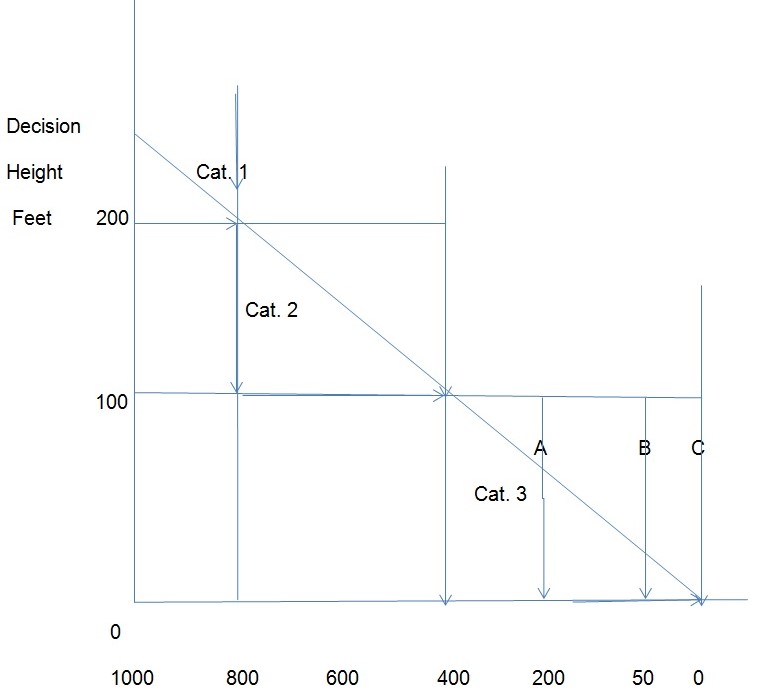
Category 1: Category 1 illustrates that there should be minimum 200ft decision height and runway visual range of 800m for the possibility of successful approach.
Category2: A high possibility of success rate is described below 200ft decision height and runway visual range from 800m, and as low as 100ft decision height and 400m runway visual range (Pallet & Coyle 1993).
Category3: Category 3 illustrates the visual range of minima 200m, with external visual reference during the final phase of the landing down to the runway.
Category3B: The visibility to and along the runways and taxiways is to be sufficient for visual taxiing equivalent to runway visual range of minima 50m (Pallet & Coyle 1993).
Category3C: No external visual reference is required to and along the surface of the runway and taxiways (Pallet & Coyle 1993).
Main Components of the ILS: The total system is divided into three parts consisting of a transmitter on the ground and receiver and signals in the aircraft. A localizer is provided for the lateral steering for front-course and back-course. Vertical navigation, for the front course, is provided by the glide slope. For getting distance checks, marker beacons are used (Powell 1981).
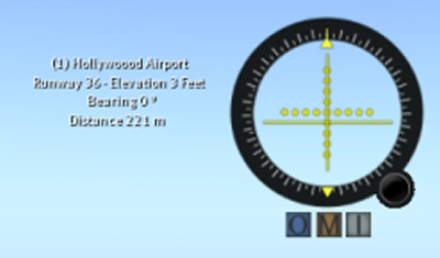
“The above illustration is depicting the vertical needle of the localizer and the horizontal needle of the glide slope. The dots are representing center of the ILS or distance from center of ILS. The round button is used for the airport selection. The signs provided by marker beacons are shown below. Important runway information is put on view in floating text beside instrument” (040_ILS Instrument Landing System n.d, Para 4).
Instrument landing system (ILS) provides accurate and reliable navigation facility to an aircraft in IFR conditions. In this system the position of the aircraft is ensured with reference to the instruments. ILS comprises four main instruments.
The above picture illustrates the sequence of 18 important tasks performed by the pilot in changing over from cruise flight to touchdown with the use of ILS (Niquette 1996).
Localizer
Ground Equipment: The localizer is the main component of the ILS. It makes the lateral guidance available. “It is a VHF radio transmitter and antenna system with similar general range as VOR transmitters (between 108.10 MHz and 111.95 MHz).The frequencies are only on odd-tenths, with 50 kHz spacing between each frequency” (Carnegie 2008, Para B.1).The transmitter and antenna are located on the centerline on the other end of the runway from the approach entrance. Some ILS systems also include the localizer back course which is normally available with a75MHz back marker facility or NDB positioned 3to 5 NM from touchdown. To ensure its positioning with specified tolerances the course is checked time to time (Carnegie 2008).
Signal Transmission: The localizer spreads out the signal in the air. These signals generate two vertical overlapping patterns identical to the shape of a fan. These patterns are aligned absolutely with the centerline of the runway. The right side of this pattern is symbolized by blue and is called the “blue” area. It is modulated at 150 Hz. The left side of the pattern which is symbolized by yellow is called the “yellow” area. It is modulated at 90 Hz. The overlap existing in the middle of the two areas is helpful in providing the signal relating to the runway. The navigational beam is regulated so as to enable about 700 ft wide track signal acquisition at the runway threshold. The localizer is recognized by a two-letter audio signal (preceded by the letter “I” for example “I-OW”) overlaying the navigational signal (Carnegie 2008).
Since the primary strength of the signal is aligned with the runway centerline, the reception range of the localizer is at least 18 NM within 10º degrees and at least 10NM between l0º to 35º of the on-track signal (Carnegie 2008).
Localizer Receiver: “There is a localizer receiver in the aircraft which functions in amalgamation with the VOR receiver in a single unit to receive signals in the aircraft. The localizer and the VOR use common electronic circuits. There is a common frequency selector, a volume control, and ON-OFF control for the two receivers” (Carnegie 2008, Para 5).
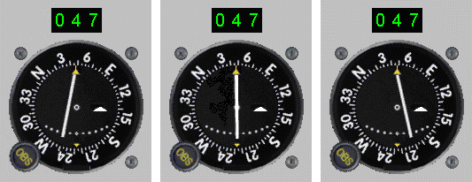
“From left to right, the aircraft is 1° Right of course, two dots (turn left to return); On course; and 1° Left of course (turn right to return)”(Wood 2008, Para 10).
“On receiving a localizer signal, the vertical needle or the track bar(TB) is set in motion. Suppose, a final approach track is aligned north and south, an aircraft taking position in the east of the extensive centerline of the runway (position 1) is in the area modulated at 150 Hz, will avert the TB to the left. On the other hand, if the aircraft is taking position to the west of the runway centerline, the 90 Hz signal the TB will deviate to the right (position 2).Force is applied to the needle by both the angles in the overlap area. This force redirects the needle in the direction of the strongest signal which helps in placing the aircraft in accurate position. The point showing equivalent intensity of both the 90 Hz and 150 Hz signals, TB being centered, indicates the precision approach” (Carnegie 2008, Para 10).
However, it is advisable that the pilot should set the track selector most of the times for the approach track. This is because the track selector setting in the localizer function is not dependable in most cases. The obstructions in between the transmitting antenna and the aircraft often cause difficulty in receiving the signals clearly. The weak signals make the vertical needle to deflect a little or indicate an OFF flag in front of it.
Glide Slope Equipment
Transmitter: “The vertical guidance for the landing approach is provided by the glide slope which is formed with the help of a ground-based UHF radio transmitter and antenna system” (Carnegie 2008). “These channels in the u.h.f. band function at a range of328.6-335.4 MHz at 150kHz spacing. The frequencies, allocated to the glide slope, are paired with the localizer frequency as both serve the same runway” (Powell 1981, p.70-71). The positioning of the glide slope transmitter is about 750 to 1,250 feet down the runway from the entrance, “offset 400 to 600 ft from the centerline of the runway” (Carnegie 2008).
The glide slope signal also consists of two beams where one beam lie on top of the other. These beams are adjusted at 90 Hz and 150 Hz. The signals spread out by the glide slope are aligned above each other and emitted mainly down the approach track. “The thickness of the overlap area is 1.4º or.7º above and.7º below the optimum glide slope.“(Carnegie 2008).
“The adjustment of this glide slope signal varies between 2º and 4.5º above a horizontal plane. In view of obstructions along the approach path and the runway slope, it is adjusted between 2.5º to 3º.Several glide path angles along the glide slope may produce false signals. The false signal approximately 6º degrees above horizontal will be a mutual signal for the fly up and fly down commands and these commands will be reversed. The false signal at 9º will be sloping just as the true glide slope. However, there are no false signals generated below the genuine slope” (Carnegie 2008, Para 11).
Signal Receiver: A UHF receiver is made available in the aircraft to receive the glide slope signals in combination with the VOR controls to receive the proper glide slope frequency by tuning it automatically when the localizer frequency is selected (Carnegie 2008).
A glide slope needle, positioned in conjunction with the TB, is set in motion by the glide slope signal. There is a special OFF flag for the glide slope needle which is visible in the navigation indicator in case of a weak signal. There is a constant deviation in the glide slope needle and it stops deflecting only after reaching that point where the signals overlie on one another. The needle deviates towards the stronger signal and slowly comes to the centered position horizontally when both the signals are equal indicating that the aircraft is proceeding in the right direction on the glide path (Carnegie 2008).
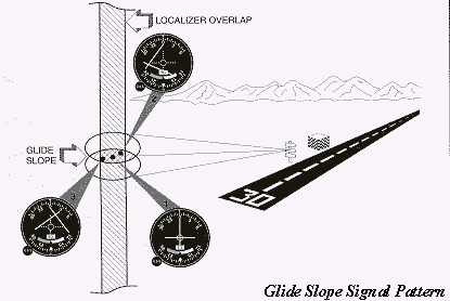
“An accurate location relative to the approach path can be accessed by referring to a single instrument. The Glide Slope Signal Pattern figure, above, position1, illustrates that the aircraft is located in the center of the approach path as both the needles are in the centered position. In Position 2 it is evident that the aircraft needs to fly down and towards the left to rectify the approach path whereas position3 is shows the requirements to fly up and towards right for catching the proper path”(Carnegie 2008, Para 12).
With the aircraft coming closer, the instrument picks up its operation accordingly. It is important that at this point of time; the pilot must monitor the deflection of the needle to know whether the aircraft is high, low or in a centered position (Carnegie 2008).
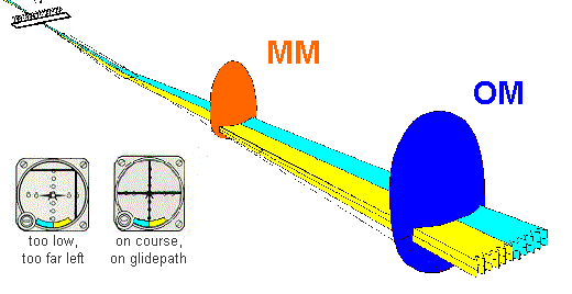
ILS Marker Beacon: The marker beacon is used for the modulation of signals. It radiates upwardly using the frequency of 75MHz (Powell 1981).These are low-power transmitters; that operate with 3 W or less rated power output. There are some preset points along the approach track in Instrument Landing System which are recognized by the marker beacons to provide information regarding distance from the runway. They radiate an oval beam upward from the ground at an altitude of 1,000 ft. which is 2,400 ft long and 4,200 ft wide and considerably increases with higher altitudes (Carnegie 2008).
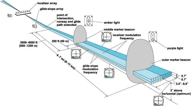
Descriptions of the ILS components
Here is a three-dimensional depiction of the Instrument Landing system. We can see the Localizer antennas close to the end of runway (Wood 2008, Para 4).
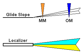
Outer Marker (OM): Within 250 ft of the extended runway centerline, the outer marker is located 3 1/2 to 6 NM from the entry. At around 1,400 ft above runway elevation a point is marked by OM crossing the glide slope vertically. It also marks the estimated point from where an aircraft starts the final approach plan. The signal is adjusted at 400 Hz, which is a low tone but easy to hear with continuous Morse code dashes. For receiving these signals, a 75 MHz marker beacon receiver is incorporated in the aircraft. The pilot can hear a tone over the speaker or headset in harmonization with flashing of a blue light. Geographical conditions may affect the positioning of the outer marker. So, a DME unit may be used to enable the pilot in making a positive position fix on the localizer. An NDB is used in place of the OM in the majority of ILS installations” (Carnegie 2008, Para 14).
Middle Marker (MM): The middle marker is located about.5 to.8 NM starting from the threshold and going along the complete runway centerline. It intersects the glide slope at about 200 to 250 ft above the runway elevation and is close to the missed approach point for the ILS Category l approach (Carnegie 2008).
Back Marker (BM): About four to six miles from the runway threshold, usually, the back course marker (BM) is located. These are located on the localizer back course. “The BM low pitched tone (400 Hz) is heard as a series of dots”(Carnegie 2008,para4).
The aircraft’s white marker beacon light is enlightened by these dots. The BM can be replaced by an NDB or DME fix quite often (Carnegie 2008).
Lighting Systems
There are many approved runway environment lighting systems in the ILS system. These lighting systems ensure the safe landing of the aircraft by providing proper visual guidance to the pilot. These are: “approach light system (ALS), sequenced flashing light (SFL), touchdown zone lights (TDZ) and centerline lights (CLL-required for Category II [Cat II] operations.)”(Carnegie 2008,para 4).Out of these any one or all the lighting systems may be provided at a specified facility (Carnegie 2008).
Runway Visibility Measurement: Before coming downwards to the decision height (DH) or the missed approach point (MAP) it is essential that the pilot has a clear view of the approach path with the help of the appropriate visual aids. The transmissometer is located adjoining the runway to provide visibility information. The photo electric cell receiver separates the light source by 500 to 700ft.The relative transparency or mistiness of the air is measured by the receiver, connected to the instrument readout in the airport tower. The readout is standardized in feet in respect of the visibility and is known as the runway visual range (RVR) (Carnegie 2008).
Runway Visual Range (RVR)
At the runway the maximum distance utilized for taking-off or landing is known as RVR. It is specified with light or markers so that it can be seen from a height matching to the pilots’ average eye-level at touchdown. It is normally expressed in hundreds of feet e.g. “RVR24”signifies that the visual range along the runway is 2,400 ft. Visibility differs in different runways so the RVR value differs accordingly. Even different points along the same runway may have varying visibility. To deal with this condition, there are many types of equipment fixed at the departure end and the central point of the runway. Runway Visual Range reports denote the capability of a pilot to have the visibility of the runway in the touchdown zone. However it is to be noted that the positioning of the transmissometer establishes the actual visibility at other points down the runway. RVR enables the pilots to decide their executions in the ultimate stages of an instrument approach. The information regarding the Runway visual range is sent to the ATC arrival control, and the control tower or FSS. The pilots are offered this information as per their requirement. The light settings can be adjusted on demand by the pilot. Two different light settings can be provided for the landing of consecutive flights. Since there are complex equipment involved, RVR is usually made available at busier airports only(Carnegie 2008).
NDBs
Supplementary aids like NDB also exist for assisting the pilot in reaching the final approach fix. It is a non-directional beacon which can be sited with the outer marker (OM) or back marker (BM) and also used to replace the OM or BM. Its transmitting power is about 25 watts (W) and frequency range is 200 kilohertz (kHz) to 415 kHz. The radio beacon can receive the signal spread out in the area of at least 15 nautical miles (NM)(Carnegie 2008).
ILS limitations
Even after providing navigation precision guidance well in the past so many years and adopting a lot of measures for improving its performance and consistency, the Instrument Landing System(ILS) has come up with certain limitations. In view of the future aviation requirements, the ILS has some basic limitations such as: “site sensitivity and high installation costs; it adopts single approach path; multi path interference; and has only 40 channels” (Carnegie 2008).
The limitations prevailing in the ILS generated a necessity of a more fool – proof landing aid that could prove to be accurate for safe landings. The following limitations in the ILS cause its degradation (Crabtree 2009).
- There are certain restrictions relative to ILS techniques and operations which affect the “flight path flexibility and airport throughput” (Crabtree 2009,para 6).
- ILS gets easily affected by signal interference due to weather and other impediments resulting in major chaos in the airport traffic, causing delays (Crabtree 2009).
- There are many ground related constraints with ILS. It requires a relatively flat terrain as ground irregularities and poor weather affect its performance (M.L.S. 1995).
- The channel range is limited to 40 channels only (M.L.S. 1995).
- ILS uses a single approach path causing much confusion and chaos in the air traffic control (M.L.S. 1995).
- It has a high user cost and is dependent on expensive ground equipment (Parkinson 1996).
- Basic ILS is suitable only for the FAA’s non precision and Category I landing requirements and only the improved ILS system can execute a landing with Category III required accuracy (Parkinson 1996).
- Moreover, the noisy ILS signals need to be processed with a smoothing filter (Parkinson 1996).
Disasters with ILS
Although, ILS has been perceived as an efficient landing aid for past so many years, inaccuracy and errors in the guidance information through this system have led to several disasters in the aviation history (Phelan 2001).
A false instrument landing system (ILS) is assumed to have caused the disastrous Korean Air Boeing 747-300 accident at Guam in August 1997.The glideslope indication may have been a chief contributory factor to this mishap. Recent studies by Air New Zealand (ANZ), have declared that the problem may have led the crew to believe that they were on the correct descent when the aircraft crashed into Nimitz Hill 5km (3nm) from touchdown. ANZ believes that the new findings indicate that 40 other controlled flight into terrain (CFIT) investigations call for review now (Phelan 2001).
“On July 29, 2000, during a standard instrument landing system (ILS) approach to Faleolo at night, an Air New Zealand Boeing 767 with 165 passengers and 11 crew on board commenced a go-around after descending to an altitude of about 400 ft, some 6 mi. short of the runway” (ILS System Failure – A Free Lesson 2010, Para 2). It was revealed after thorough investigations that flawed guidance information was being transmitted by the ILS glide path (GP) transmitter. The cockpit GP and localizer indications were normal. The Civil Aviation Authority (CAA) of New Zealand has publicized the matter widely so as to warn the ILS operators about the risks involved with this approach. Hence, a valuable insight into the recognized weakness in ILS systems is provided by this serious incident. It has annunciated the necessity to adhere to ICAO standards and guidance material during ILS operations and maintenance to avoid extreme hazards (ILS System Failure – A Free Lesson 2010, Para 2).
Another instance indicating the failures of the ILS system came into light when a First Air Boeing 737-200, registration C-GNWN performing flight 7F-6560 from Yellowknife, NT to Resolute Bay, NU (Canada) went missing. It was flying with 11 passengers and 4 crew members. Later on it was found crashed while on approach to Resolute Bay. Only 3 passengers survived with injuries (Hradecky 2011).
The progress report released by TSB confirmed that the aircraft using ILS approach to runway35T was reported 10 miles visibility in the light drizzle with overcast cloud at 700ft AGL whereas it was found to be 5miles visibility in the light drizzle with overcast cloud at 300ft.AGL just after the crash. The crew started a go-round for 2 seconds and then impacted terrain at396ft.MSL whereas the runway level was 215ft. MSL. The impact was approximately1nm east from the middle point of the runway. There were no technical errors found in the aircraft before the impact but the ILS was confirmed to be serviceable (Hradecky 2011).
The weakness of the ILS system was observed critically when guidance signals were reflected due to two consecutively landing aircrafts resulting in false guidance. This may not be so dangerous if the weather conditions allow the pilot of the following aircraft to see the runway ahead. The weakness of the ILS relative to false signals was considerably experienced at London’s Gatwick airport years ago. “MD-80 crew decided to make a practice “hands off” ILS auto land approach and touchdown while following a Boeing 737 to land on Gatwick’s single runway. Everything was going on smoothly, but the 737 landing in front positioned its vertical fin and rudder straight in the beam of the ILS localizer antenna when it was about to reach the runway threshold. The beam deflection gave a false impression that the MD-80 had rapidly drifted off the beam” (Evans 2003, Para 5). The crew immediately took over the autopilot and thus averted a terrible accident. This resulted in the considerable increase in separation between following aircrafts and affected the runway throughput to a great extent (Evans 2003).
Microwave Landing System (MLS) was then taken into consideration seriously, since the MLS scanning beam take no notice of reflected signals. So, MLS-equipped aircraft can maintain normal spacing on their operations regarding the final approach. The capacity levels which is decreased due to low –visibility periods can be improved with the application of MLS as a standard landing aid (Evans 2003).
NATS airport services director, Peter Wilde puts the advantages of MLS in this way-“Heathrow airport is among the busiest in the world and MLS is expected to bring benefits to both our airline and airport customers” (Evans 2003, Para 6).
The limitations of ILS in performing a landing procedure of an aircraft may be hazardous occasionally. So, a replacement system i.e. MLS, suggestive of overcoming the weaknesses of the ILS, has been recognized as a standard precision approach (Evans 2003).
Microwave Landing System
The MLS became functional in the airports in 1988 and was approved for use in international civil aviation until at least the year 2020.It is adopted mainly in North America and Europe to support low-visibility instrument precision approach and landing operations. In addition to the fixed-base MLS equipment design, a compact mobile microwave landing system (MMLS) equipment design exists. The instrument landing system (ILS) is also standardized internationally and approved for use indefinitely as countries implement their transition to new technologies (Vickers &DiBenedetto 2008).
MLS description
These systems provide more directions than the ILS which enable the pilots to select suitable path for their type of aircraft to descend and land. The different landing patterns can abate the noise problem around the airports. Further, the option of multiple paths prevents the small aircrafts from the risky vortices that are formed if a large aircraft is flying ahead. In Europe, MLS has been taken up to be used in place of ILS. In the U.S. the FAA is taking into consideration a technology supported by the global positioning systems (GPS); an exceptionally accurate satellite based navigation aid (Mola n.d.).
Microwave Landing System is more accurate in improving air safety than the instrument-landing system. It is appropriate for the autoland approaches where the aircraft is controlled by the equipment as it allows safer landings in extreme weather, with zero visibility (Perlman 1987).
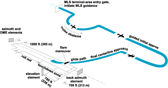
Here is an illustration of the landing operation with microwave landing system units located near the runway. The elevation element is sited such that the glide path crosses the threshold above 50 ft (15 m) (Vickers &DiBenedetto 2008).
The time-referenced scanning beam Microwave Landing System (MLS) is recognized by ICAO as the standard precision. Accurate precision navigation guidance is provided by this system relative to the alignment and landing of aircraft.
Five ways of function
The system is functional in five ways: “Approach azimuth; Back Azimuth; Approach elevation; Range; and Data Communications” (Carnegie 2008, Para2).
Approach Azimuth Guidance: In the MLS system the position of the approach azimuth antenna is generally about 1000 feet beyond the finishing point of the runway (Carnegie 2008).
The MLS offers scanning of the narrow beams clockwise then counterclockwise for azimuth functions and up then down for elevation functions, providing a large coverage volume. A lateral sector of maximum 60° on each side of the runway centerline and a vertical sector of maximum 30° is scanned electronically at an exact rate of 20,000°/s. The airborne receiver interprets the angular position of the aircraft by measuring the time gone between successive passages of azimuth or elevation beams (Vickers &DiBenedetto 2008).
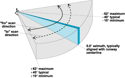
Here is an illustration of the maximum, typical, and minimum values of the magnitude of the azimuth at the limits of the coverage volume (Vickers &DiBenedetto 2008).
Back Azimuth Guidance: The back azimuth antenna enables the aircraft to acquire lateral guidance in cases when the approach and departure navigation is overlooked. The back azimuth transmitter broadcasts at a slightly lower data rate because the guidance accuracy needs are comparatively flexible here. Moreover, the equipment operates on the equivalent frequency for both approach azimuth and back azimuth except for the difference in the time utilized in transmission sequence. The azimuth equipment can be switched in their operation from the approach azimuth to the back azimuth and the other way round on runways with MLS approaches on both ends (Carnegie 2008).
Elevation Guidance: “Both the elevation station and the azimuth station transmit signals on similar frequency. Between the entrance and the touchdown zone the elevation transmitter is located at about 400 ft. on the side of the runway permitting the pilot to choose from a wide range of glide path angles” (Carnegie 2008, Para 15).
Range Guidance: “The MLS precision DME (DME/P) makes the range guidance available relying on the accuracy provided by the azimuth and elevation stations. DME/P has an accuracy of +100 ft as compared, with + 1200 ft accuracy of the standard” (Carnegie 2008, Para G).
Data Communications: This data transmission includes both basic data that contains approach azimuth path and smallest glide path angle and supplementary data which contains additional approach information such as runway condition, wind-shear or weather (Carnegie 2008).
Principle of Operation
The MLS system operates at a frequency band of 5031, 0 – 5090, 7 MHz on two separate channels at a mutual interval of 300 kHz. The protractor part of the MLS offers information about the exact position of an aircraft in relation to the runway in the horizontal and vertical plane. The distance between an aircraft and the reference points in the approach process is measured by the rangefinder part of MLS. The on –board antenna provides the angular information about the approach course, descent flare and go-round. This process includes the measuring of the period between two courses of swinging plane lobe.
All parts of the MLS are coordinated maintaining a synchronized timing of the transmission’s individual data blocks. Distance related information is received separately on an interconnected DME channel. A separate monitor circuit is equipped in each part of the MLS system to deal with intolerable deviation. However, the pilot needs to inform the traffic control in case of a persistent deviation (Principle of Operation 2012).
So, getting accurate information about the position of an aircraft facilitates the landing procedures. (Principle of Operation 2012).
MLS Advantages
It is evident that ILS has limitations which bar or confine its use in many circumstances. MLS not only eliminates these problems; but also offers many advantages over ILS including (Blake 1985):
- MLS has only one signal quality standard which is equivalent to ILS category III enabling a pilot to land in most adverse conditions. The cost of providing category II/III can be reduced to a great extent which is a chief benefit over ILS.
- This will certainly enhance the capacity by making more and more locations available for operations under these categories. Further, the expenses on special training and installation of extra equipment will be saved.
- There is no requirement of a smooth terrain in front of the elevation antenna hence, there is more flexibility regarding the location of the antenna to avoid runways and taxiways to break through the critical area.
- The MLS signal is less sensitive to natural impediments like rising and falling tides, deep snow; rising vegetation and the varying weather conditions.
- Moreover, the MLS digital signal is less susceptible to signal variations. Its integrated circuitry provides signal processing at a reasonable cost and the special processing circuit in the receiver provides resistance to signal disturbances.
- Another characteristic of the MLS is that the effects of the signal reflecting objects can be curtailed through controlled scan and modification of the transmitted signals. This feature makes MLS more flexible to the runway environment avoiding flight disruptions.
- MLS installation at the locations where it was not feasible previously can be beneficial for the enhancement of traffic flow for following the Instrument Flight Rules (IFR).
- Further, the improvement in designing procedure will result in reduction in flight times and airspace conflicts due to the curved signal approach whereas ILS offered only straight line approach to the runway.
- The Back Azimuth Guidance offered by the MLS is quite helpful in the development of precision missed approach and departure procedures resulting in the establishment of an efficient air traffic system (Blake 1985).
- The problem of ILS/FM broadcast intrusion is resolved with the application of this system.
- It provides ‘all-weather’ coverage up to ±60 degrees from runway centreline, from 0.9 degree to 15 degrees in elevation, and out of 20 nautical miles (NM) (Carnegie 2008).
- MLS has the potential to provide precision guidance to small landing areas such as roof-top heliports.
- It presents a wide range of glide paths so that STOL and VTOL aircraft and helicopters and be accommodated.
- MLS bestows an upgraded guidance quality which does not require much path corrections (Carnegie 2008).
The above mentioned benefits of the Microwave Landing System, consequently, help in improving airline punctuality and airport capacity. UK aviation safety regulator, the Civil Aviation Authority granted permission for the first ever operation such kind at a commercial airport (Heathrow) in the low visibility conditions (category III). Both ends of Heathrow’s two runways are equipped with the MLS equipment (World’s First ‘Low-Visibility’ Microwave Landing System in Operation at Heathrow 2009, Para 4).
The British Airways Director of Flight Operations Captain Stephen Riley expresses the significance of the MLS system as: “This pioneer initiative will mean less disruption and congestion, which is great news for our customers” (World’s First ‘Low-Visibility’ Microwave Landing System in Operation at Heathrow 2009, Para 4).
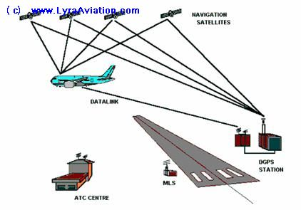
The MLS has been chosen over ILS in Europe but the U.S. F.A.A. is working on providing two augmentations to the GPS to facilitate the civil aviation with space based navigation, switching from the ground based radio navigation aids. The first one known as the Wide Area Augmentation System (WAAS), focuses on the vast prevalence of the user needs and averts the requirement of conventional, ground-based radio navigation aids. The second one known as the Local Area Augmentation System or LAAS, introduced later, fulfills the precision approach and landing needs that cannot be fulfilled with WAAS. It complies and operates successfully with the WAAS. Both are based on differential techniques that involve correction for the common errors in between the reference stations and the airborne receivers. The WAAS is a network of these reference stations spread over hundreds of miles whereas the LAAS focuses on individual airports. It consists of reference stations spaced tens of meters (1 m = 3.3 ft) apart and a line-of-sight data broadcast with a service volume of approximately 50 km3 (12 mi3) (Swider, n.d. ).
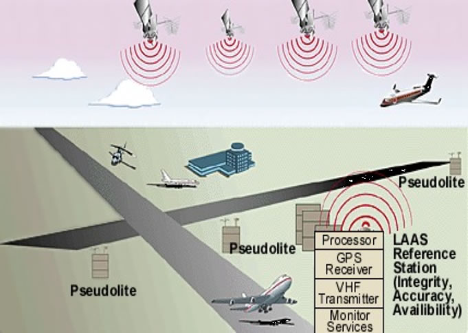
Local Area Augmentation System
LAAS description: LAAS, the “Local Area Augmentation System” is similar to DGPS. Working in combination with a ground station, like DGPS, it can get better accuracy than WAAS for a small area. An extra hardware is required with it to receive the special signal. LAAS has not been made functional because WAAS only is accurate enough for CAT 1. LAAS can be used in the areas where WAAS doesn’t reach, such as mountains blocking WAAS signals (Claborne 2001).
Principle of Operation: It works in connection with a single station, providing GPS facility to the airport being serviced. LAAS is outfitted with three or more reference receivers. These receivers measure the GPS satellite pseudo range and carter phase. “These receivers then generate differential carrier-smoothed-code corrections that are
Eventually broadcast to user via a 31.5-kbps VHF data broadcast (in the 108 – 118 MHz band) including safety and approach-geometry information. This information allows GPS-based position fixes with 0.5-meter (95%) accuracy within 45 km of the LAAS ground station. Aircraft landing at a LAAS-equipped airport perform precision approach operations up to at least Category I” (Konno 2006, Para 1).
“Although it has become easier and uncomplicated now to compute and broadcast differential GPS corrections, the aircraft safety in designing and fielding LAAS is still a crucial issue and requires a verification to a probability of two in ten million (2e-7) per approach for Category I and one in one billion (1e-9) per approach for Category III so as not to exceed a safe error bound known as the alert limit. Moreover, the possibility of approaches to be cancelled due to detected failures or false alarms must be below one in one hundred thousand (1e-5) per 15 seconds. This verification is done by LAAS Ground Facility or LGF by detecting and excluding abnormal reference receiver measurements before the broadcast of differential corrections. These corrections that are broadcast come with bounding standard-deviation values (“sigmas”) on errors in the corrections that enables the users to verify the safety and conduct of their current operations by computing and comparing position error bounds known as ‘protection levels’ with them” (Konno 2006,Para 2).
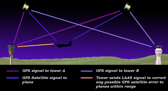
There are two clocks in the LAAS ground station which download the GPS data from all accessible satellites and compare it to the tower’s position, its own position and subsequently calculate the error ratio between the two clocks. All the aircrafts coming within the range are sent these modified signals which help in close in manoeuvres around an airport (Local Area Augmentation System n.d.)
Wide Area Augmentation System
WAAS description: The Wide Area Augmentation System (WAAS) is developed to work in association with the Global Positioning System. This system is a great aid in the functioning of the GPS as it improves the accuracy, integrity and availability of this system in air navigation. It enables the GPS to perform efficiently for all phases of flight. With the help of a single receiver it can provide significant information about the exact positioning thus resolving many problems related to navigation. This system enables an airport to have a precision approach at a very low cost.
“WAAS performs efficiently between the airports allowing the aircraft to fly straight from one airport to another. Further, the special feature of WAAS has been observed in finding the shortest route available. This characteristic is quite helpful in some cases saving time and fuel” ” (Wide Area Augmentation System n.d, Para 2). “WAAS equipped aircrafts can fly at lower en-route altitudes because they receive information on the accuracy of each GPS satellites opposed to the ground-based systems. This system improves the safety of the unpressurized aircrafts by conserving oxygen” (Wide Area Augmentation System n.d, Para 2). Apart from providing convenience this system plays a significant role in the relative cost reduction (Wide Area Augmentation System n.d).
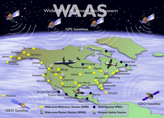
There are 39 ground reference stations in the continental U.S. and parts of Canada and Mexico under the FAA’s Wide Area Augmentation System (WAAS) GPS-based navigation network. Two master stations along with three more stations for data transmission are also included within it. Positions accurate within 25 feet are made available to the pilots using WAAS. It can also guide a descending aircraft to a vertical height of 200 feet before landing, providing instrument approaches in bad weather (Watson 2007).
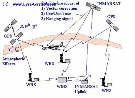
Principle of Operation: WAAS is a system of satellites and ground stations offering GPS signal corrections. The position accuracy made available with this system is considerably high. Besides being precise it is economical too. It does not require any additional receiving equipment. WAAS was developed in collaboration by the United States Department of Transportation (DOT) and the Federal Aviation Administration (FAA), beginning in 1995 for providing precision approach capability for aircraft. It helps in removing tribulations like ionospheric disturbances, clock drift (timing), and satellite orbit errors that create too much error in the GPS signal.
GPS satellites send signals that are received across the NAS at many Wide Area Reference Stations (WRS) sites. The WRS locations are accurately inspected to detect errors in the received GPS signals (WAAS- Wide Area Augmentation System n.d.).
A terrestrial communications network helps in moving forward this information to the WAAS Master Station (WMS). The WAAS augmentation messages are generated here containing information relative to the errors. This information helps considerably in removing errors in the GPS signal consequently increasing location accuracy and reliability. These messages are connected to the stations to be transmitted to navigation payloads on Geo stationary communications satellites.
The augmentation messages are broadcast by the navigation payloads on a GPS-like signal which are processed by the GPS/WAAS receiver and help in estimating position. The signals about the non-functionality of WAAS in certain areas are also provided to GPS/WAAS receivers (WAAS- Wide Area Augmentation System n.d.).
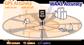
FAA (Federal Aviation Administration) and the DOT (Department of Transportation) are working in collaboration towards the development of WAAS so that the flight locations can be made more accurate. The navigational requirements of the FAA require GPS to be supported by WAAS in its functioning as has proved to be five times more accurate than the normal GPS. The best quality of WAAS is that it is built in to some GPS systems which make it cost-effective as no additional equipment is required for it to function properly. Moreover, the GPS can be upgraded to have WAAS capabilities (Tower 2006).
Several problems come across GPS when used alone like ionospheric disturbances, precision timing, and orbit errors for the satellites used. These three crucial problems, besides some smaller ones, are corrected when is supported by WAAS. In case of the satellite not working properly WAAS can offer information on satellite itself (Tower 2006).
Currently, WAAS enabled GPS systems provide most accurate information in open land or at sea. The signals are very clear near the equator as the stationary satellites are at the equator or if they are not being blocked by mountains, trees, or other natural and manmade objects. WAAS technology may not be perfect at present but offers much more capability than the existing systems. In course of time it will prove to be one of the most important technology systems for GPS receivers (Tower 2006).
Advantages of LAAS and WAAS: Global, standardized navigation services for all types of aircraft operations and all phases of flight can be made available with the use of differentially corrected GPS service, with the help from the WAAS or the LAAS. Such kind of information is very helpful in making navigation easy and effortless for aviators, reducing the expenses and providing more well-organized, flexible procedures. Common receivers for en route, terminal, and approach navigation results in considerable cost reduction. It is noteworthy that it leads to the minimization of terrestrial-based assets that have to be procured and maintained, yielding benefits and savings (Swider n.d.).
FAA’s NextGen navigation program: SmartPath
SmartPath description: The replacement of ILS with the Ground Based Augmentation System (GBAS) or SmartPath has been acknowledged crucial for the enhancement of the air traffic capacity in the FAA’s Next Gen system and Euro control’s Single European Sky ATM Research Programme. The Smart Path, introduced by Honeywell, is a ground based augmentation system dealing with GPS corrections in technical and operational limitations present in the Instrument Landing System (ILS) improving flight path flexibility and airport throughput (Crabtree 2009).
Vicki Panhuise, Honeywell Vice President, US Defense Customers says “One SmartPath system installed in a typical airport can yield annual maintenance savings of up to $400,000 compared to a single ILS. Honeywell’s technology offers airports improved efficiency and capacity, while offering operators greater navigational accuracy and fewer weather-related delays” (Crabtree 2009, Para 5).
A GPS receiver equipped plane makes navigation easier but still needs some assistance from the ground when it comes to rapid descending of an aircraft quite near to the ground. SmartPath provides assistance to GPS-enabled navigation and is an effective system to refurbish air-traffic control. It can save a lot of time by relieving congestion in the most crowded hubs. Moreover, it enables the planes to fly closer simultaneously without getting affected by the weather conditions. The GBAS proves to be significant in using the sky immensely and more proficiently. (Lindsay 2009).
“GBAS is meant for precision approach, departure procedures, and terminal area operations”(Navigation Services – Ground Based Augmentation System (GBAS) 2010,para 3).
It will provide high precision level and convenience and also the remarkable dependability which is essential for Category I, II, and III precision approaches. The use of flexible and curved approach paths will enhance the worthiness of this system. “GBAS confirmed accuracy is less than one meter in both the horizontal and vertical axis” (Navigation Services – Ground Based Augmentation System (GBAS) 2010, para 3).
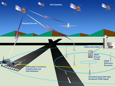
Principle of Operation: There are four to 13 GPS satellites that send microwave signals to the GBAS or SmartPath. “The most difficult thing isn’t determining the plane’s GPS position, but ensuring SmartPath doesn’t cause any errors,” said Honeywell’s T.K. Kallenbach.
The four GPS antennae mounted around the airport can locate almost anywhere without getting affected by any interference. The raw feed is accurate within 10 meters and the finished product including data on the planes within a 23-mile radiuses specific to one meter. The approach paths are transmitted to the planes through a VHF antenna, using the corrected coordinates which in turn pass to an onboard multimode receiver. This on board multimode receiver analyses, validates and represents the ILS radar, GBAS data, and the plane’s own GPS. This enables the pilot to receive the information without any interferences and disturbances. The approach paths logged by the pilot are recognized by GBAS which in turn broadcasts 26 different paths to incoming planes and guide them in ILS radios one. So, lot of noise and fuel is saved as these weave around the neighborhoods. Smaller planes will be able to coast over the “wake turbulence” and use shorter stretches of runway for landing. GBAS proves to be more beneficial when the runway is not visible. ILS, air traffic control spaces planes to greater extent influencing its precision. Honeywell estimates airports lose up to 25% of capacity during bad weather (Sheble 2009).
A GPS receiver gets data at the rate of 50 bits per second as it keep tracking satellites. The data containing information about navigation message and time of transmission can be classified into observations, meteorological data and navigation. In GPS -based surveys a single set of sessions is sufficient for collecting large quantities of data (Dhunta 2008).
However, it is very important that the GPS receiver process the received data in real time. Accurate position information can be produced by keeping observations data in memory of a given size, statistical techniques, smoothing and filtering. This data can be processed after the observations so that with the help of advanced software can be applied to get the best positioning results. Thus, GPS is a well-advanced science, which can be applied only after adequate training (Dhunta 2008).
Advantages and cost saving
- The SmartPath Precision Landing System provides differential GPS corrections and integrity for all satellites in view and approach path information covering all runway ends.
- The closely-spaced parallel and curved path approaches can be used for landing with the SmartPath accuracy.
- This system provides superior navigation accuracy than the Instrument Landing Systems (ILS).
- One SmartPath system installed in a typical airport can yield maintenance savings of up to $400,000 annually when compared to ILS.
- It is more flexible than ILS as one GBAS can broadcast 26 unique approaches at a time boosting the air traffic control at the airport.
- It utilizes differential GPS, and information regarding both pseudo range corrections for each satellite in view, as well as approach path is broadcasted digitally.
- All ends of all qualified runways can be covered using GBAS whereas the ILS requires additional installations for complete coverage.
- This system provides offset and segmented approaches for those aircrafts which have displaced threshold landings.
- GBAS avionics are being equipped or are being offered as an option in maximum current production Airbuses and Boeing aircraft (SmartPath- The next generation of precision landing guidance technology 2011).
A characteristic feature of SmartPath system is that it provides multiple approach paths improving airports and facilitating their capacity without any need of expansions of the runways. Kallenbach, Honeywell Aerospace Vice President, Marketing and Program Management states that “The precise approach path can allow airports to reduce noise in surrounding communities while operators save fuel and lower emissions” (Crabtree 2009, Para 5).
The FAA is working together with the other countries of the world towards international GBAS implementation. Different countries in the world are adopting and implementing the GBAS system in the field of aviation. For example: “Air services Australia, DECEA in Brazil, DFS in Germany, and AENA in Spain have been actively supporting the implementation of GBAS”(Navigation Services – Ground Based Augmentation System (GBAS)2010).
These countries are concerned about the installation of model GBAS systems and also working to bring about the substance relative to the technical and operational evaluation of these systems. Although these nations are developing their own approval and certification processes but are still aiming to act in accordance with FAA approval practices (Navigation Services – Ground Based Augmentation System (GBAS)2010).
“GBAS, described as SmartPath by Honeywell, is the initial stage of an infinite plan to refurbish air-traffic control. A long -term alternative to GBAS is to build more runways to increase the number of takeoffs and landings. Adding runways and realigning them will require a huge amount of money. For instance, 13 billion and 20 years will be spent in the proposed renovation of Chicago’s O’Hare to increase the number of takeoffs and landings by 20%.The characteristic feature of GBAS is that it provides these facilities in reasonably low prices proving to be a cost-effective system in the aviation industry. It is estimated that about $9billion a year is wasted on the unmanageable delays of flights in the U.S. airlines. The losses that the airlines suffer due to congestion can be converted into profits by using GBAS, apart from offering a safe and pleasant flight” (Lindsay 2009, Para 4).Honeywell Aerospace president and CEO Rob Gillette states, “We’re trying to help the airlines fly well and really synchronize their operations into and out of congested airports” (Lindsay 2009, Para 4).“SmartPath is supposed to be functional at 600 airports by 2020 at a base price of $2.5 million apiece, producing $1.5 billion in revenue” (Lindsay 2009, Para 4).
Currently, aircrafts take up Instrument Landing System (ILS) technology which has many technical restrictions affecting the suppleness of the flight path and airport throughput. Its signals are easily influenced by bad weather conditions and other impediments including large aircraft like the A380.The signal interferences may cause significant disorder in the airport traffic. Thus, FAA’s NextGen program and Euro control’s SESAR programs have considered adopting SmartPath
GBAS in place of ILS for improving the state of air traffic (Crabtree 2009).
According to TK Kallenbach, Honeywell Aerospace Vice President, Marketing and Program Management “The improved safety from the accuracy and stability of the approach provided by Honeywell’s SmartPath GBAS versus the older ILS technology is one of the major benefits to pilots” (Crabtree 2009, Para 4). “A single GBAS can support landing operations on multiple runways simultaneously, eliminating the need for multiple ILS systems at airports with more than one runway. This new system will reduce acquisition and maintenance cost while providing aircraft operators and airports with safer and more efficient operations” (Crabtree 2009, Para 5).
Autoland
The limitations of older technologies in ensuring safe landings where only short-length airstrips are available due to deserts or vegetated areas and in rough seas, led to the development of autoland system(Satellite Navigation & Air Traffic Control and Landing Systems (SATNAV & ATCALS) 2012).
The existence of the automatic landing systems dates back to June 1965, with British Airways having made the first automatic landing during a commercial flight in using an automatic flare controller in the pitch axis. Further, in 1966 a landing with full control in all three axes was accomplished.
System description
In today’s commercial Autoland systems the ILS’ vertical and lateral guidance is employed to descend. In this operation the aircraft’s track is kept in agreement with the runway centerline. The aircraft comes into the flare mode at around 30 ft above the ground, during which the aircraft pitches up to trim down the vertical speed from its current descent rate to 1-3 ft/s by touchdown. The automatic landing system used in the aircraft is certified to either category CAT I, CAT II or CAT III, which is based on the minimum altitude above the touchdown zone. This minimum altitude is defined as the decision height (DH) and the pilot must have the runway in sight from this point and be able to see as far down the runway as per the RVR. In case of not having an appropriate visual range, the pilot has to execute a missed approach and go-round in order to land or divert to another airport. The on-board and the ground-based equipment must, be certified to at least the specific category in order to be able to perform an approach in that specific category. General aviation aircraft level equipment is typically certified to CAT I only, requiring the decision height at about 200 ft and about 1,800 ft runway visual range. So, the general aviation autopilot system is taken over at 200 ft and the landing is performed manually. Whereas, the commercial aircraft are capable of CAT III certified automatic landing equipment which is again categorized as CATIIIa, CAT IIIb and CAT IIIc (Siegel &Hansman 2011).
CAT III generates the need of surplus auto-flight systems including additional ways of activating all flight controls and surplus auto pilots. In order to work out the problems usually related with the conventional flight control systems, the concept of ‘system redundancy’ was taken up. It refers to a multiple system operation in such a way that there will be trivial effects of a single system failure on the performance of an aircraft during the approach and landing procedures (Pallet & Coyle 1993).
For the accurate measurement of the distance over ground, redundant radar altimeters are mandatory. The hardware cost of this type of equipment is exorbitant for most private operators debarring its use in the aviation aircraft but commonly found on commercial aircraft (Siegel &Hansman 2011).
An aircraft needs to be controlled well to achieve a safe landing. It should be able to touch the ground with its wheels at a sinking speed of an optimum value of about 1-2 feet per second. The speed at touch-down should be reduced to the half value of the approach margin which is 30% above the stall. Eventually, the wings should be paralleled before the actual landing and the aircraft is yawed to match its longitudinal axis with the center-line of the runway to avoid any drift angle due to cross-wind. It is important to control all three axes of the aircraft simultaneously along with controlling the airspeed with engine power. So, it is obvious that the approach and landing are most crucial tasks in aircraft operations. Unfortunately, most of the accidents are due to the approach and landing phase of a flight. It is essential that better guidance and control should be provided by the systems designed for automatic landings under all visibility conditions. The approach and landing maneuver is needed to be controlled repeatedly. Several factors are required to be controlled simultaneously for a very short period of time which can be easily executed by the automatic means (Pallet & Coyle 1993).
Aims &Objectives
The development of the automatic landing system was required since the existing approach and landing systems were not providing satisfactory results in this field. So, in view of keeping the safety levels high and counter the problems relative to the systems in current use, the automatic landing system was reckoned as the best possible option. The following objectives can be achieved by adopting the automatic landing system.
- Achieving the optimum level of integrity and reliability of systems by trusting their capability in controlling an aircraft along with the throttles, and in the presence of the ground.
- To provide sufficient monitoring information regarding the progress of the approach and landing manoeuvre so that the pilot can handle the critical conditions of a system break down in the presence of the ground.
- The provision of an integrated and reliable automatic ground guidance system to substitute the pilot’s direct vision (Pallet & Coyle 1993).
“The term ‘all- weather conditions’ is frequently associated with the automatic landing systems” (Pallet & Coyle 1993, p.280).It does not mean that an aircraft cannot be prevented from taking-off and landing in any kind of weather conditions. It refers to those extreme conditions for which the aircraft has been certified on grounds of its controllability and strength factors. Further, the runway conditions due to malfunctioning, also limit the power of automatic control systems(Pallet & Coyle 1993).
Principle of Operation
The landing phase of an aircraft’s flight is fully automated in an autoland system. The pilot only supervises the process and performs a monitoring role during the final stages of the approach. He intervenes only in cases of a system failure or emergency and, after landing, to taxi the aircraft off the runway and to the parking location (Autoland 2011).
“However, in some autoland systems the aircraft has to be steered by the pilot during the rollout phase on the runway after landing (such as Boeing´s fail passive system on the B737NG), as the autopilot is not connected to the rudder.
The aircraft is steered first through the rudder and then through the nose wheel steering (NWS) in autoland system. A full stop can be made on the center line connecting to the auto brake, without pilot intervention. In case of unavailability of NWS the pilots are dictated to control the aircraft through the rollout disconnecting autopilots immediately on touchdown” (Autoland 2011, Para 2).
Different climate and weather conditions affect the approach and landing phase of an aircraft considerably. Autoland systems were designed to enable the pilots to make landing possible even when the weather conditions were not supportive and influenced the visibility to a great extent. There are many components and systems, such as “the autopilots, auto thrust, radio altemeters and nose wheel steering that work in amalgamation to accomplish the process of auto landing” (Autoland 2011,para4).The auto brake system is often used along with an automatic landing even though it is not an integral part of it (Autoland 2011).
“The aircraft flight control is supplied with the necessary inputs and then the power settings of the engine are adjusted for sustaining the required approach contour and land the aircraft safely without any involvement of the pilot. Though, at times it becomes compulsory that the pilot get involved to deactivate the thrust in the procedure of auto landing. However, it is highly advisable that the pilot must go for a reverse thrust settings in all cases” (Autoland 2011, Para 4).The pilots deactivate and take over the autopilots after landing to taxi the aircraft to the finishing point of the runway (Autoland 2011).
The TOGA switches can be pressed to withdraw the approach at any time. However, the disconnection at this point solely depends on the aircraft type or autopilot system installed. The pilot of an aircraft, having an autoland capability, can opt for the go-round process provided both autopilots engaged are fulfilled (Auto land 2011).
Landing Operation
“The operation of the autoland system depends on the number of channels that are armed or engaged performing ‘LAND 2’ status or ‘LAND 3’ status autoland. ‘LAND 2’ signifies the dual redundancy (fail passive operations) and ‘LAND 3’ signifies the triple redundancy (fail operational)of power sources, engaged flight control computers, sensors and servos. This status is displayed on an autoland status annunciator” (Pallet & Coyle 1993, p. 283).
In the indicator, the actual autoland potential of the AFCS is indicated on the upper display and the degradation from ‘LAND 3’ capability is indicated on the lower display.
The control system operates as a single channel system during journey and initial stages to land. The pitch and roll axes of the aircraft are controlled and proper flight director commands are given by the control system. The other two channels are armed by switching ‘APPR’ on at a certain stage of the approach as multichannel operation is needed for an automatic landing. By doing this the localizer and glide slope modes are also fortified (Pallet & Coyle 1993).
A radio altimeter provides the information relative to vertical guidance to touchdown through signals. These signals become prominent on reaching the altimeter’s functional range (typically2, 500feet)(Pallet & Coyle 1993).
On descending 1,500 feet radio altitude the localizer and glide slope beam are captured and their signals control the roll and pitch axes of the aircraft so that deviations can be corrected to maintain alignment with the runway (Pallet & Coyle 1993).
Simultaneously, the auto land status annunciator displays ‘LAND2’ or ‘LAND3’ as per the selection of the channels for landing the aircraft and the computerized control of flare is also armed.
The aircraft is trimmed to a nose-up attitude when its horizontal stabilizer gets automatically repositioned on descending at a radio altitude of 330ft. Subsequent pitch control is provided by the elevators in the trimmed attitude by turning aside.
On reaching the gear altitude (45feet above the ground) the flare mode is automatically engaged controlling the pitch attitude from the glide slope, and making a pitch command to get the aircraft onto 2feet/second descent path. In the meantime the auto throttle system is commanded to reduce the engine thrust to the limits well-suited with the flare path. The transition from the flare mode to the touchdown and rollout mode takes place at about 5 feet gear altitude. The pitch attitude is again decreased at about 1foot gear altitude, and at touch down the elevators are supplied a command signal to lower the aircraft’s nose and to bring the nose landing gear wheels in contact with the runway and hold them there during the rollout. The auto throttle system is automatically disengaged on applying the reverse throttle keeping the AFSC in control until the flight crew disengages it (Pallet & Coyle 1993)
Guidelines for the airliners
The airliners must consider some guidelines before authorizing its crews to perform automatic landings.
“With CAT II or CAT III ILS qualify beam, the Automatic Landing System performance has been established, nevertheless automatic landing on CAT I ILS quality beam is feasible only if the Airline has checked that the guidance below 200ft is satisfactory. The ILS ground equipment quality should be checked properly. It is also essential to know that there are no specific restrictions relating to CAT I only competence. Terrain profile significantly affects the automatic landing system performance so the runway threshold has to be taken into account” (Getting to Grips with CAT 2 CAT 3 2001, p.15).
There must be some standards set up by the airline regarding authorization of pilots for automatic landings. Only listed runways can be used for the purpose of an automatic landing. The measures and techniques similar to CAT II / CAT III
operations must be established by the operator. Flare, landing and roll-out must be strictly observed as the crew has to be ready to take over in these flight phases. However, it is always up to the crew to decide to continue the automatic landing or to take over manually or to go around (Getting to Grips with CAT 2 CAT 3 2001).
Conclusion
To achieve a smooth and secure landing of an aircraft, a number of navigational aids can be used by the pilot. The routine inspection of various navigation aids has led to many developments and improvements in the instrument procedures. Global Positioning System (GPS) technology has emerged as a capable satellite-based positioning navigation basis for many of the ground-based navigation systems to be used in the years to come. Though, the designing cost of the approach path for ILS, MLS and GPS is almost same, the GPS proves to be cost effective as it reduces flight times and fuel consumption. Furthermore, the information received through GPS offers more accuracy and safety. The implementation of differentially corrected GPS service, with the support of WAAS or the LAAS, provides standardized navigation services for all types of aircraft operations and all phases of flight.
Other advancements in avionics such as the GBAS or Smartpath introduced by Honeywell and the autoland system suggest an increasing role for flight inspection possibilities for the navigational and landing aids in the future. The replacement of ILS with the Ground Based Augmentation System (GBAS) or SmartPath has been acknowledged crucial for the enhancement of the air traffic capacity in the FAA’s Next Gen navigation program.
Reference List
040_ILS Instrument Landing System (n.d.) Drusilla Saunders Aeronautics [Internet], Web.
Autoland (2011) Sky Brary [Internet], Web.
Blake N A (1985) Concerning the Microwave Landing system and the Traffic Alert and Collision Avoidance System [Internet], Web.
Carnegie C (2008) Microwave landing system (MLS) Navigation Systems-Level 3 [Internet] Web.
Carnegie C (2008) The Instrument Landing System Navigation Systems-Level 3 [Internet] Web.
Claborne C (2001) Answers for GPS+ WAAS and other stuff GPS for Pilots. Web.
Crabtree K (2009) Honeywell Provides Satellite Precision Landing System for Bremen Airport Honeywell [Internet] Web.
Crabtree K (2009) Honeywell Provides Satellite Precision Landing System for Qantas A380 Landing at Sydney Airport Honeywell [Internet] Web.
Crabtree K (2009) Technology Allows Airports to Increase Capacity, Reduce Delays, Improve Energy Efficiency Honeywell [Internet] Web.
Dhunta P S (2008) GPS Data Processing Principles of GPS (2004-2008) [Internet]
Evans B (2003) MLS: Back to the Future? Avionics Today [Internet] Web.
Getting to Grips with CAT 2 CAT 3 (2001) Sky Brary [Internet] Web.
Horne T A (2011) Normal Approach and Landing Flight Training [Internet] Web.
Hradecky S (2011) Crash: First Air B732 near Resolute Bay on Aug 20th2011, impacted terrain [Internet] Web.
ILS System Failure – A Free Lesson (2010) Transport Canada [Internet] Web.
Konno H (2006) Local Area Augmentation System (LAAS) GPSLAB [Internet] Web.
Lindsay G (2009) Honeywell’s GPS-based Landing Tech Could Save Airlines Billions Fast Company [Internet] Web.
Local Area Augmentation System (n.d) [Internet] Web.
M.L.S. Issue 2, Vol. 3, The School of Aeronautical Engineering, Brunel College of Arts and Technology, Bristol, UK
Mola R (n.d.) Aircraft Landing Technology U.S. Centennial of Flight Commission [Internet] Web.
Mola R (n.d.) History of Aircraft Landing Aids U.S. Centennial of Flight Commission [Internet] Web.
Navigation Services – Ground Based Augmentation System (GBAS) (2010) Federal Aviation Administration. Web.
Nirjharini (2011) Essential Aspects of Flight School Ground Course on Landing Bright Hub [Internet] Web.
Niquette P (1996) Chapters in the Sky [Internet] Web.
Pallet & Coyle (1993) Automatic Flight Control, Blackwell, UK
Parkinson B W (1996) Global Positioning System: Theory and Applications, Volume II, Chapter 14, The American Institute of Aeronautics and Astronautics [Internet] Web.
Phelan P (2001) ILS trap ‘may have caused’ Korean Boeing 767 to crash into Guam hillside Flight Global [Internet] Web.
Perlman J A (1987) John Wayne Airport to Get Microwave Landing System Los Angeles Times [Internet] Web.
Powell J (1981) Aircraft Radio Systems, JEPPESEN
Principle of Operation (2012) [Internet] Web.
Satellite Navigation & Air Traffic Control and Landing Systems (SATNAV & ATCALS) (2012) ARINC [Internet] Web.
Sheble N (2009) Smart technology could save airlines billions InTech [Internet] Web.
Siegel D & Hansman J R ( 2011) Development of an Autoland System for General Aviation Aircraft [Internet] Web.
SmartPath- The next generation of precision landing guidance technology (2011) Honeywell. Web.
Swider R J (n.d.) Local Area Augmentation System (LAAS) McGraw Hill [Internet] Web.
Tower C 2006, What is WAAS? Lockergnome [Internet] Web.
Vickers & DiBenedetto (2008) Microwave landing system (MLS) McGraw Hill [Internet] Web.
WAAS- Wide Area Augmentation System (n.d.) Navigadget [Internet] Web.
Watson B (2007) New System Makes Bad-Weather Flying Easier for Pilots Space [Internet] Web.
Wide Area Augmentation System (n.d) MSPAero [Internet] Web.
Wood C (2008) The Instrument Landing System [Internet] Web.
World’s First ‘Low-Visibility’ Microwave Landing System in Operation at Heathrow (2009) Airport International [Internet] Web.