Introduction
The following subsections of this study explain the purpose, as well as the contextual background in relation to the systems compared herein.
Purpose
The following report compares flight control systems of a conventional fixed wing aircraft and rotor blade helicopter. Pilots utilize flight control systems while flying aircrafts, in order to control direction, attitude among other forces affecting flights.
A control system is basically a collection of electronic and mechanical equipments, which allow aircrafts to be flown with particular precision, as well as reliability [2]. The basic components of flight control systems consist of sensors, computers, cockpit controls, and actuators which can be mechanical, hydraulic or electrical [2].
The flight control systems and their characteristics differ greatly. The variances depend on the type of aircraft being flown. Apparently, most of the basic flight control systems have mechanical designs that date back to the early models of aircrafts. The operations of some of these systems are based on collection of mechanical parts. The mechanical parts include cables, rods, and pulleys. In some aircraft models, chains are used to transmit forces from the flight deck controls, to the system control surfaces.
Background
Aircraft Flight Control Systems Background
In most cases, aircraft flight control is achieved through two major systems. The two are mechanical and hydraulic systems [4]. Flight dynamics essentially explain almost all types of aircraft flight control systems. And the basic system was first used in 1908, which is on Louis Blériot’s Blériot VIII pioneer-era monoplane design [5].
The basic design for the modern aircrafts flight control systems was pioneered by Robert Esnault-Pelterie and Louis Bleriot [7]. Both individuals have been very instrumental in advancing development of flight control systems in the aviation industry.
Helicopter Flight Control Systems Background
Helicopter flight control systems development is traced back to Samuel Langley, Otto Lilienthal, and the first fully controlled flights by Wilbur and Orville Wright as early as 1903 [6]. The systems are believed to have been developed simultaneously with the development of an aircraft which could vertically lift from the ground, although the details are less clear.
Mechanisms Description
The subsections which follow describe the various aspects of aircraft flight control system, and helicopter flight control system. The description entails appearance of the systems, component parts and assemblies, as well as how they operate.
Aircraft Flight Control System
Aircraft Flight Control System Appearance
A basic flight control system irrespective of being for helicopter of fixed wing aircrafts consists of key components. The components include cockpit controls, actuators which can be electrical, mechanical or hydraulic and computers, as well as sensors [2]. Due to the differences in the design of helicopters and fixed wing aircrafts, there are some significant differences in flight control systems.
Figures 1-3 illustrate the appearance of aircraft flight control system:
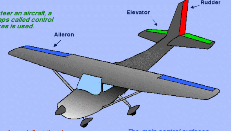
Aircraft flight control system components
Aircraft flight control system consists of primary and secondary system (see figures 1-3). The primary system consists of ailerons, rudder, and elevators [2]. The secondary system on the other hand consists of wing flaps, trim systems, leading edge devices, and spoilers [2].
The main components of an aircraft flight control system consist of the control surfaces (see figure 1). Other components include a collection of mechanical parts such as tension cables, rods, counterweights, and in some cases chains used to transmit forces from the cockpit controls to the control surfaces (see figure 3 and 2).
Ailerons
The main function of ailerons is controlling the aircraft’s roll, around its longitudinal axis [2]. Ailerons attach to each wing on the outboard trailing edges, whereby they move in opposite directions from one another [5].
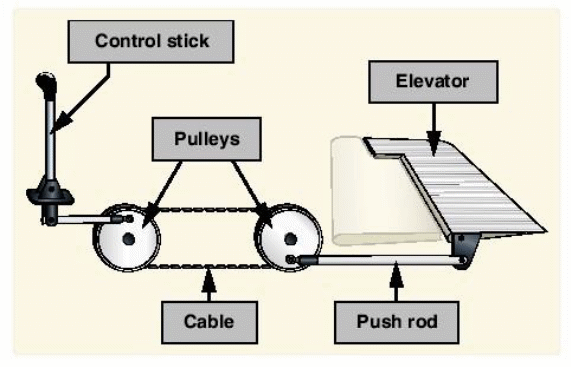
Control Stick
The control stick also known as the control wheel connects to the ailerons through cables, pulleys and or push-pull tubes, as well as bell cranks [2]. Movement of the control stick in various directions causes deflections in the ailerons. On the other hand, the left aileron is deflected downwards [5].
The deflections on the ailerons are important. They determine the direction in which the aircraft moves. For example, deflecting the right aileron upwards causes a decrease in camber. Subsequently, the deflection results in decreased lift, with regard to the right wing. Ultimately, the aircraft rolls to the right due to the decreased lift on the right wing, and increased lift on the left wing [5].
Elevator
The elevator has the function of controlling pitch about the aircraft’s lateral axis []. The elevator also connects to the control column in a similar manner to the ailerons; mechanical linkages [2]. The adjustments made on the control column results in movements on the trailing edges of elevators’ surfaces. They lead to either upward or downward deflection.
Rudder
The function of the rudder is controlling the aircraft’s movement about the vertical axis, through movement referred to as the yaw [2]. Similar to the other primary control surfaces, the rudder is also movable, since it is hinged on a movable surface held on a fixed surface [5]. The fixed surface can either be the fin, or a vertical stabilizer [7]. Movement on the right or left rudder pedals facilitates control of the rudder [5].
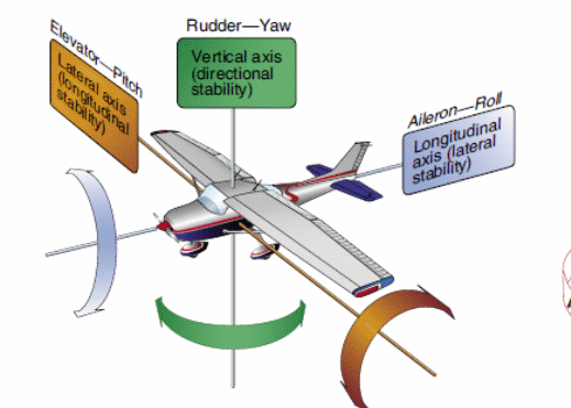
Figure 4 provides an illustration of the movements by the various components of a flight control system:
Wing Flaps
They constitute the most commonly high-lift secondary flight control system devices utilized on aircrafts [2]. Flaps surfaces are important components. They are attached to the trailing edges of the wings [5]. Flaps strike a balance between two forms of speed. The two are high cruising and low landing speeds [5].
Spoilers
Spoilers are also secondary flight control systems devices, which are deployed from the aircraft’s wings. Spoilers play a number of purposes. For example, they help in smoothing airflow and enhancing drag. In addition, they reduce lift [2]. The other function of spoilers on aircrafts includes roll control [2].
Aircraft flight control system operation
Flight control systems are utilized by pilots in controlling the forces of flight, the aircraft’s attitude, and direction [2]. In most aircrafts, the basic flight control systems are usually mechanical, and they date back to the earliest aircrafts.
The control column located in the cockpit is apparently the major coordination point of aircraft flight control system. The pilots interact with the flight control system through the system computers, and the more significant control yoke.
The airplane is made to fly in a particular direction, height and speed through the coordinated effort exerted into the flight control system through the control yoke/column [5]. After the aircraft has been powered, the roll and pitch of the aircraft are governed through the control column and the centre or side sticks [5]. The control column moves the ailerons, or activates warping of the wings depending on the design of the aircraft [2].
The rudder pedals or the rudder bar in earlier aircraft models is used to control yaw, which in turn controls the movement of the rudder [5]. For instance, moving the left foot forward translates to leftward movement of the rudder as well. Throttle controls are finally used to regulate the speed of the engine. In other words, they control the thrust of the craft.
Although aircraft flight control systems have some standard or conventional features, control yokes vary depending on the design of the aircraft. For instance, some aircrafts are controlled through rotating the yoke either in clockwise or anticlockwise direction. In others, pitch can be controlled through tilting of the control column either away from, or towards oneself (see figure 2).
The aircraft’s pitch in some models is also controlled by either sliding the yoke into or out of the instrument panel [2]. Roll control in aircraft flight systems is achieved by sliding the yoke either to the left or right [5]. Centre sticks also exhibit differences both designs, as well as operation, depending on the aircraft’s model. In some aircrafts, the control surfaces are connected directly to the centre sticks using cables hence requiring considerable effort by the pilot in controlling the flight. In recent aircraft models however, the control surfaces are linked with the control column through a computer which hooks to some electrical actuators, hence enabling automated flight control.
Helicopter Flight Control System
Helicopter Flight Control System Appearance
Helicopter flight control systems and the fixed-wing aircraft flight controls have very significant differences. The differences are mainly due to the fact that helicopters are rotary wing aircrafts, which makes them more complex, since they are basically very non-symmetric machines [3].
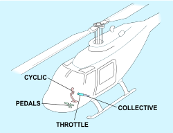
Unlike the winged aircrafts, helicopter flight control systems are very different in that the systems have only three separate main controls. The major flight controls for helicopters include the cyclic pitch control, the collective pitch control and the tail rotor or antitorque pedals control [3]. Helicopter pilots must coordinate all these major control during flight. Helicopter pilots are also required to utilize the throttle control mounted directly on collective pitch control during flight, although this is not a part of the flight control system [3].
In some helicopter model or complexity, the collective and cyclic controls are mounted together, through a mixing unit [3]. The mixing unit is apparently a hydraulic or mechanical device, which combines the input of both controls, and then transmits the effort to the control surfaces for desired effect [6]. Some helicopters are fitted with governors, through which pilots control collective pitch on the main rotors, hence facilitating stable and accurate flights [6]. Some helicopter models have no governors. Such models manual throttle’s are considered part of flight control system, since they help in maintaining rotor speeds.
Figure 5 below illustrates the helicopter flight control system:
Helicopter flight control system components
Figure 5 indicates the various components of the helicopter flight control system. Each of the components is very significant in ensuring that pilots are able to appropriately control the helicopter’s flight. The individual components of helicopter flight control system and their functions are as follows:
Collective pitch control
The collective pitch control is also known as thrust lever. The location of the collective pitch control is the left side of the pilot’s seat, so that it is operated on using the left hand [3]. The main function of the collective pitch control is making changes to the helicopter’s pitch angle of the rotor blades either simultaneously or collectively [3].
Raising the collective pitch control results to a simultaneous and equal increase in the pitch angle of the main rotor blades [6]. Lowering the collective pitch control results in an equal decrease in the pitch angle of the main rotor blades [3]. The level of pitch control attained through series of mechanical linkages, which determine the amount of blade pitch change [6].
Varying the pitch angle on the blades of helicopters has a number of impacts. For example, it changes the angle of incidence for the remaining propellers. The change in the angle of incidence creates a change in drag, which eventually has an effect on the main rotor’s revolutions per minute [6]. The combined effects created by the collective pitch control results in the helicopter increasing or decreasing the total rift derived from the rotor blade or blades.
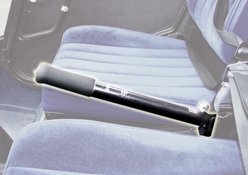
Throttle control
The main function of throttle control is regulating the engine’s revolutions per minute (rpm) [3]. Correlators or governors helps in maintaining desired rpm, during instances when the collective throttle is either lowered or raised. If this is not the case however, the throttle must be manually moved using the twist grip, in order to maintain rpm [6]. The throttle control apparently works in a similar manner to the motorcycle throttle hence, twisting it to the left increases rpm, while the opposite is true.
Figure 6 below illustrates a helicopter’s flight system throttle control:
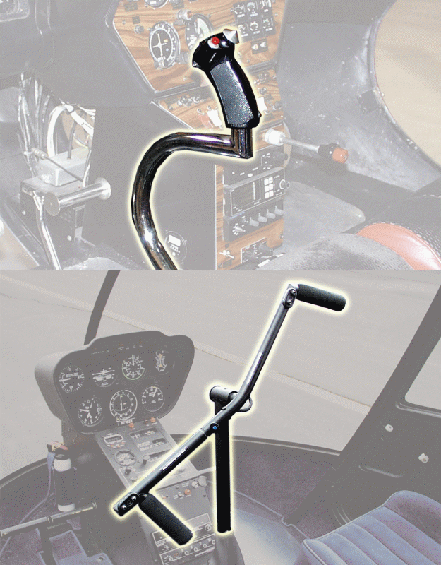
Cyclic Pitch Control
They are important aspects of the craft. The control system is usually located on the floor of the cockpit. It is projected upward between the two pilots’ seats. It may also be located between their legs [6]. The cyclic pitch control allows helicopter pilots to fly in all directions of travel; forward, rearward, right and left [6].
Flight aerodynamics postulate that total lift force is invariably perpendicular to the tip-path of the plane’s main rotor [3]. Cyclic pitch control tilts have an impact on the tip-path. To this end, they enable the pilot to direct the aircraft to the desired direction.
The cyclic controls regulate the rotor disk tilt, versus the horizon [4]. Consequently, the rotor disk thrust is oriented towards the particular desired direction. The pilot is hence able to control the helicopter’s direction of travel. The rotor disk tilt is closely related with other components. Such components include the cyclic pitch control. For instance, if the movement of the cyclic is forward, then the rotor disk is also stilted forward.
Figure 7 below illustrates where the cyclic pitch control is located. In some models, the component is mounted vertically between the controller’s seats. In other models, it is located on swiveling bars. The bars are found at the center of the copter.
Correlator or Governor
It is another important component. It regulates the revolutions of the rotor and the engine [3]. Under normal circumstances, the RPM is adjusted once. The governor maintains the revolutions. As such, there is no need for throttle changes [3].
The component is commonly found in all turbine helicopter crafts. However, a number of piston powered copters do not use them [6]. Correlators on the other hand are mechanical connections between the engine throttle, and the collective lever [6]. Collelators also facilitate system maintenance of desired value of rpm.
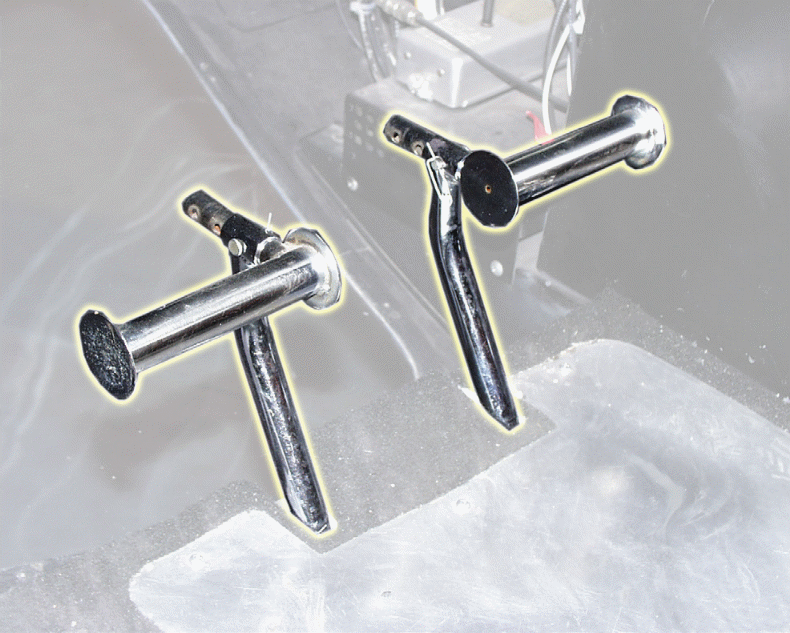
Antitorque pedals
The antitorque pedals are located on the cabin floor next to the pilot’s feet resting [6]. The function of the antitorque pedals is controlling the pitch, as well as the thrust from the tail rotor blades among other antitorque systems [6]. The antitorque pedals are based on Newton’s Third Law. To this end, an action should elicit an equal and reverse reaction [6].
The law applies to helicopter’s fuselage and the rotation in opposite direction to the main rotor blades for counteraction and control [6]. Majority of helicopter designs have a tail or antitorque rotor. The idea is to compensate for torque and make flight possible. The antitorque pedals hence allow helicopter pilots control pitch angle of the tail rotor blades [6]. For instance, forward thrust puts the machine on a longitudinal hover. However, the pilot can make a 3600 turn [6].
Figure 8 below illustrates helicopter flight control antitorque pedals:
Helicopter flight control system operation
The helicopter pilots utilize flight control system so as to achieve the desired controlled aerodynamic flight [6]. The various components of the helicopter flight control system are managed by the pilot. The effects are mechanically transferred to the rotor. Consequently, aerodynamic effects are produced on the rotor blades of the helicopter, allowing the aircraft to be controlled as desired [1].
Tilting the helicopter back or forward (pitch), or tilting it sideways (roll), requires the angle of attack of the rotor blades to be cyclically altered during rotation [6]. The consequent effect is creation of differing extents of lift or elevation at differing points in the cycle [6]. The helicopter’s lift can be increased or decreased. The objective is achieved by manipulating the flight control system. As a result, the orientation of all the blades changes. In this case, the slant of attack is altered collectively. It is also altered in equal amounts. The flight control systems effects ascents and descents, as well as accelerations and decelerations [3].
Comparative Analysis
The subsequent subsections of this study compare aircraft flight control system and helicopter flight control system. The basis for the comparison is the ability of each of the systems to perform the core function of controlling a flight, their efficiency, as well as cost.
Operational goal
The operational goal of any flight control system is basically ensuring that an aircraft can be flown with exceptional precision and with reliability [7]. Any flight control system that does not meet this core functionality is regarded as ineffective and unsuitable for any use.
Assessment Criteria
Performance
Any type of flight control system, irrespective of whether developed for fixed wing aircrafts or helicopters must be able to facilitate accuracy and precision during flight. The system should be able to facilitate various forms of flight maneuvers, as well as ensure ability to fly under various flight conditions.
Efficiency
An effective flight control system is not determined by the level of power consumption. On the contrary, the efficiency of a flight control system is determined by the rate or ease with which the system is able to control the aircraft during flight. For instance, one aspect of flight system efficiency is speed with which control surfaces respond to the control column in fixed wing aircrafts flight control systems.
Cost
In most instances, the cost of a flight control system does not play a major in assessment, due to the sensibility of the same. However, the cost of a flight control system increases based on the complexity, type and aircraft model, hence leaving no proper basis for the determination of the best price.
Discussion
The subsequent subsections ascertain the level with which the compared flight control systems meet the assessment criteria.
Aircraft flight control system discussion
Aircraft flight control systems are relative effective in controlling flights in fixed wing aircrafts. Apparently, the cost of the system varies depending on the technology applied in the system. Although most of smaller aircrafts use mechanical systems, these systems have been linked with computer in the control column, making the systems highly effective.
Aircraft flight control systems provide greater automated capabilities such as automatic piloting, as opposed to their counterparts in helicopters. The systems are also not very effective in cases where the aerodynamic forces tend to be more excessive.
Helicopter flight control system discussion
Helicopter flight control systems render more capabilities to these rotary winged aircrafts as opposed to the counterparts in fixed wing aircrafts. Helicopter flight control system allows the lifting without any requirement for forward movement, hence allowing for vertical takeoff and landing. In addition, helicopter flight control system allows hovering, a capability which fixed wing flight control systems cannot achieve. Consequently, helicopter flight control systems are more effective in accomplishing tasks that fixed-wing aircrafts cannot achieve.
Concluding Recommendation
The comparative analysis makes it apparent that aircraft and helicopter flight control systems do share some basic dynamics. However, the suitability of a flight control system is based various factors such as type of aircraft (rotor-blade or fixed wing), as well as the size of aircraft. Helicopter flight control systems however exhibit some maneuvering capabilities which lack in the other system. Aircraft flight control systems also exhibit more automated capabilities than helicopter flight control systems.
References
Helis, Flying a helicopter, Helicopter History Site, 1997 [Online].
Federal Aviation Administration, Flight Controls, 2011 [Online].
Federal Aviation Administration, Helicopter Flight Controls, 2011 [online]. Web.
P. Greenspun, Learning to Fly Helicopters, 2003. .
Woodward, Woodward Aircraft Flight Control Systems, Woodward, 2012 [Online]. [6] J. G. Leishman, Principles of Helicopter Aerodynamics, Cambridge: Cambridge University Press, 2000.
A. Garg, R.I. Linda and T. Chowdhury, “Evolution of Aircraft Flight Control System and Fly-By-Light Flight Control System”, International Journal of Emerging Technology and Advanced Engineering, vol. 3, no. 12, 2013, pp. 60-65.