Introduction
Turbine performance utilities require performance enhancements due to the rapid and unforgiving increase in energy demands calling upon engineers to design and develop energy efficient techniques to optimize power output for energy producing utilities. Among the most reliable technologies for enhancing gas turbine performance in hot and humid climates is the technique of cooling the inlet air using techniques such as fogging and evaporative cooling as discussed in this report. It is clearly a technical and performance advantage to cool air at the inlet leading to the modification of the density of air at the inlet with the aggregate effect of improving the performance of a turbine or power generation utility. That is in consideration of the fact that temperature rises during summer in hot climate regions impair the performance of a power generating utility by reducing the density of air at the intake. One characteristic influencing factor as to the choice of cooling technique to adopt is the ambient ratio of the humidity of air and the density as critical factors. Among the technique is the fogging technique and evaporative cooling as discussed in this paper.
Inlet Air Cooling Systems in Hot and Humid Climates
Gas Turbine Fogging
An extensive application of the fogging technique particularly in power generation utilities leads to the optimization of power production with a rapid payback particularly when using the fogging technique at the inlet of a gas turbine. The impact on the performance of a fogged inlet turbine is influenced by a number of performance determining parameters. Holman (1997) and Johnson (1989) concur that these parameters include the temperature at the inlet of a turbine, the mechanical efficiency of a gas generator, the optimum speed that can be attained by the gas turbine, the temperature of exhaust gases, and the pressure at which the turbine compressor discharges gas in relation to the rate at which fogging is applied at the inlet of the gas turbine. Further arguments by the Technical specification of the project, design, manufacturing, and installation of media evaporative
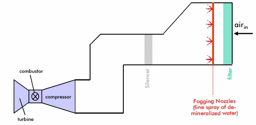
cooling system for 6 units of Fars combined cycle power plant (2002) report indicates that gas turbine fogging draws on the use of demineralized water with the objective to reduce the applied water into minute droplets using specially engineered nozzles for the purpose of producing atomized water droplet sprays at very high pressures. The technique is aimed at producing fog at the inlet of a turbine during the evaporation process with the consequent objective of cooling the air at the inlet as illustrated below (Cortes, & Willems, 2003).
It has been demonstrated that the cooling efficiency due to fogging at the inlet of a turbine is close or at least almost one hundred percent effective. However, the resulting cooling efficiency is also influenced by the design constraints of the inlet of a turbine and other design variables such as the typical design of the compressor aimed at achieving efficient wet-bulb temperature values. Johnson (1989) provides an overview of a typical high pressure gas turbine (Chaker, Meher-Homji, Mee, 2002).
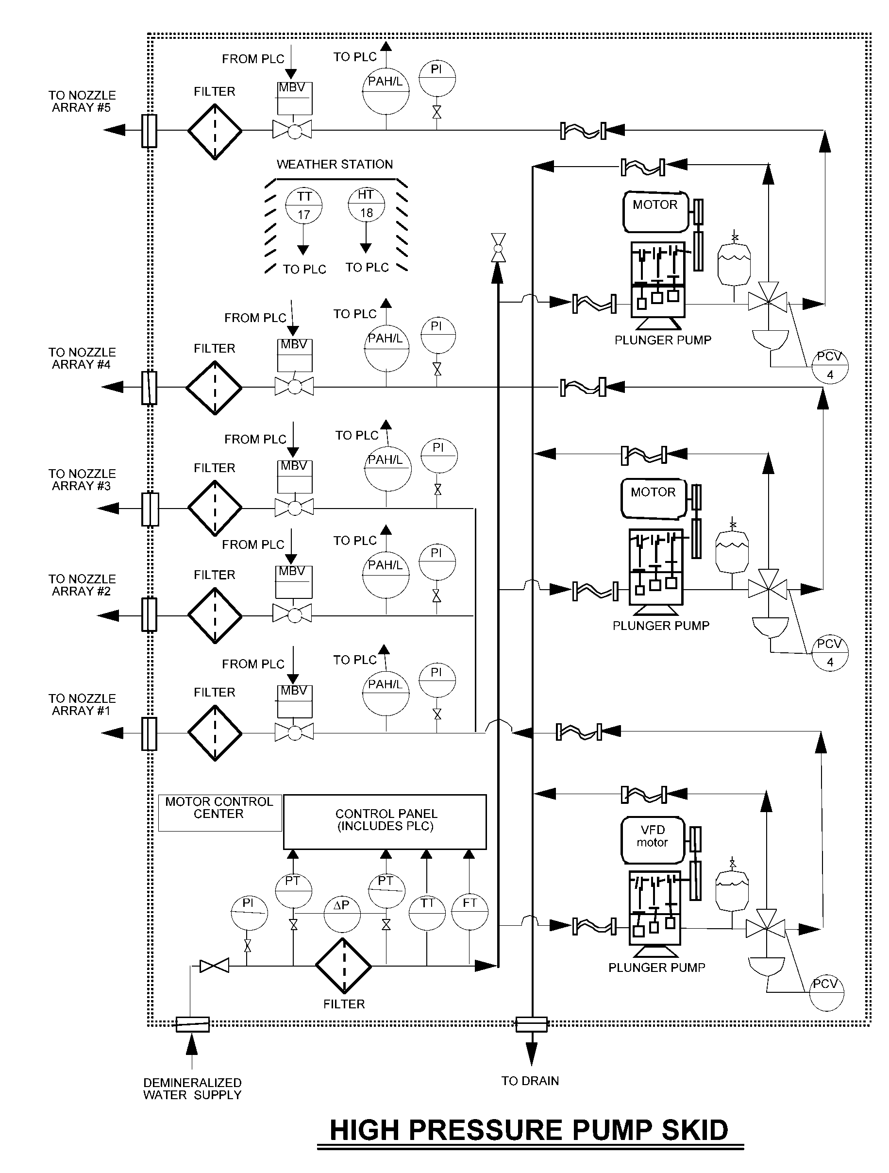
Johnson (1989)’s argument is based on a typical fogging system design that consist of high pressure pumping compartments organized sequentially to provide high pressure water to several nozzles designed to provide excellent fogging effects on the high pressure water from the array of high pressure reciprocating pumps. As an engineering requirement, high pressure plays the critical role of forcing the demineralized water into droplets through the application of very high pressures on the atomizing nozzles. In response to the high pressure water, the fogging effect results from the creation of a large number of droplets whose physical characteristics are influenced by a number of parameters such as the pumping pressure, the number of nozzles in the arrangement of nozzles, and the orientation of the turbine itself to the nozzles (Technical specification of the project, design, manufacturing, and installation of media evaporative cooling system for 6 units of Fars combined cycle power plant, 2002) and (Brooks, n.d).
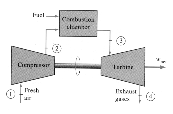
Bradury, Hancock and Lewis (1963) demonstrate the fact that in a typical fogging environment, large gas turbines show the need to be equipped with a large number of nozzles with the overall effect of creating a fogging effect equivalent to the fogging demands on the turbine inlet to optimize the density of the inlet air. Moreover, the use of demineralized water is critical to avoid the possibility of fouling compressor blades and the aggregate corrosion effect of mineral water and high temperature gases on a turbine’s construction materials. A typical example of a gas turbine is illustrated below (Grabe & Chappell, 1974).
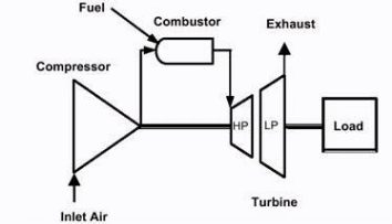
The above diagram demonstrates a practical application of the fogging effect in the respective engineering fields of application. It can be clearly discerned in the diagram that the turbine is a two shaft design with the effect of applying the fogging technique at the inlet to improve its performance (Brooks, n.d). Typically, the turbine is largely used in gas or oil industries. In addition to that, it provides a basis for further studies on the application and enhancement of turbine performance using the fogging effect on the inlet gases in the discussion, as an industry application (Grabe & Chappell, 1974).
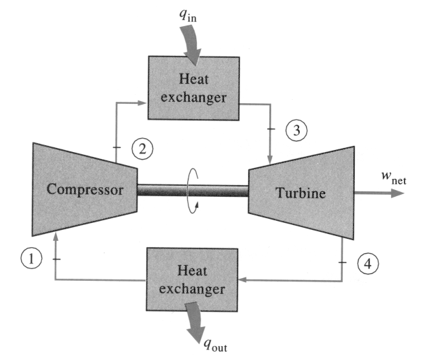
Analytically, it is worth noting that the performance of a two shaft turbine is strongly correlated with the compressor and the respective turbine efficiency. The correlating or matching variables are defined by the gaseous flow in the turbine, the temperature of the flow and pressures that can be achieved in the turbine. That also relates to the equilibrium conditions that are attained between the compressor and the turbine. Other influencing variables include work output, the degree of compatibility of the flow, and optimum speeds achieved by the rotating turbine and the compressor (Boonnasa, Muangnapoh & Namprakai, 2006).
The speed of the rotating turbine and the compressor in all types of engines such as a multiple spool and free spool engines must be in equilibrium for efficiency to be attained. Besides that, the flow of gas in a turbine is continuous hence the demand for compatibility in the flow. There is also need to establish an equilibrium condition between power outputs from the compressor and the input torque from the driver shaft. A typical example of the arrangement is illustrated in the above diagram.
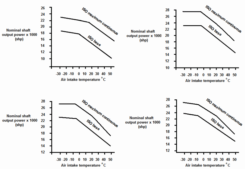
Different turbine designs used in different environments demand varying conditions and equilibriums conditions. In addition to that, an overall critical factor in the performance of these varied models is the relationship between the ambient temperature and the maximum speed that can be attained at optimum working conditions. However, some turbines and engines are designed based on ISO standards. In that case, the ambient temperature is a function of the optimum rotational speed that can be attained by the turbine. As the ambient temperature rises, the driver turbine’s power experiences a decrease. However, the driver turbine efficiency curve can be improved by orienting the geometry of the turbine to optimize power outputs in relation to the effects of the ambient temperature. Therefore the overall effect of the ambient temperature on the performance of a turbine is worth discussing here (Arrieta & Lora, n.d).
The Effect of the ambient Temperature
It has been demonstrated that the ambient temperature attained by a gas has a mathematically inverse relationship with the inflow rate and the drop in temperature of the inlet gas. Arrieta and Lora (n.d) note that the drop in temperature has the effect of increasing the density of the flow with the ultimate effect on the volume of the flow and power output. From a practical perspective, lower temperatures causes an increase in mass flow influencing an increase in power output. However, it has been observed that as the operating conditions become intense, nozzles choke and the increase in mass flow appreciates the pressure ratio of the operating environment leading o the overall drop in performance of the give machine (Boonnasa, Muangnapoh & Namprakai, 2006). However, a practical evaluation of the operating environment indicates that maximum operating pressures can be attained irrespective of the level to which the inlet air is cooled. The limiting variables are defined by the degree of compressor discharge pressure that can be attained by the compressor’s mechanical speed, and the temperature of the turbine blades. It is a practical consequence to realize that power drops can be experienced to a minimum knee point for some turbines particularly aero-derivative propulsion machines. However, experimental evidence indicates that power drops are significant when the ambient temperature appreciates under a range of temperature values. However, under practical working conditions, a number of issues have to be considered when designing an inlet fogging system with the aim of improving the ultimate performance of a turbine in a typical environment (Cortes & Willems, 2003).
Practical Considerations
One of the critical elements to consider is the effect of foreign object damage. Under practical working conditions, it has been demonstrated that the possibility of damage due to icing at the inlet cooling point is rive. For that reason, the fogging system should be designed and inculcated with the ability to cease from fogging the inlet gas in the event of icing at the inlet. The icing is commonly caused by temperature that reaches a statically depressive state with the accelerating air as the driving force (Cortes & Willems, 2003).
Another critical engineering factor to consider is the effect of duct drainages (Shah, 1978). This element plays a critical role based on their strategic positioning in relation to the bell mouse and the silencer components. The design has an overall impact on the performance of a turbine therefore calling on careful design considerations. It is important to mention here that the design should be drawn from experience, actual turbine configurations, and other restrictions that might eventually cause water to accumulate at the duct. It is also important to consider incorporating silencers that have draining capabilities built into them (Shah, 1978).
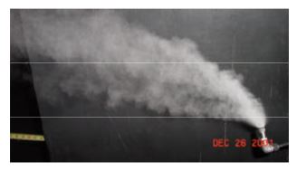
It has been demonstrated that the nozzles have to be oriented as discussed above to achieve optimal fog distributions. That is in addition to determining the arrangement of the array of nozzles that are used in the fogging process as illustrated below (Fairman, 1962).
In a typically practical environment, it is important to consider issues such as nozzle distribution, appropriate location for nozzles in a fogging system, and the distribution of nozzles within the fogging system with the sole aim of optimizing the efficiency of the fogging system. In the views of Shah (1978), practical studies indicate that the design of the nozzle, it orientation, and other engineering considerations are aimed at achieving a uniform distribution of droplets with the ultimate goal of achieving uniform distribution of the inflow mass. However, the orientation of nozzles in a fogging system is critically influenced by the inflow velocity of the air mass, the line separating the nozzles, pressures that are achieved at the mouth of the nozzle and the respective spray patterns, and the geometry of the respective duct (Shah, 1978).
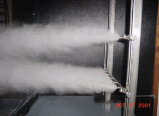
Empirical evidence demonstrates that nozzles can vary in their orientation. It has been shown that these orientations vary between zero degrees and 90 degrees in relation to the inflow mass. However, for practical applications, research shows that a 90 degree orientation and orienting a nozzle towards the inflow mass are not viable options and should be avoided. It has been recommended that an orientation between zero and 60 degree are viable and practical options. Experimental results are illustrated on the behavior of the fogging spray below.
Compressor surge is another factor to consider for optimizing the performance of a turbine in relation to the fogging effect more particularly for the engineering systems that are fog inter-cooled. Engineering estimates clearly indicate that the spraying effect at the inlet for a fog inter-cooled turbine causes an overspray above the value that is allowed under the turbine’s operating requirements. The overall effect moves the compressor’s operating points and an engine’s operating point towards the surge line. Even with heavy duty gas turbines, the surge line shifts by a specific value. In addition to that, a number of factors influence the surge condition. Among the critical factors include the design of the gas turbine blades and the overall fouling effect on the blades. A typical arrangement of high pressure design is illustrated below.
Engineers know quite well that any engineering project must have goals that strategically focus on the needs of the customer and the user of the technology under consideration. To that end, therefore, fog cooling must be characterized by goals that focus on attaining the best benefits from the cooling system. Therefore, fog cooling comes with specific goals. Among these goals are selecting the best option to achieve the best investment. In addition to that, the technology should achieve the best financial benefits with the shortest payback period, user and needs driven designs, excellent fabrications on a system, and a clear and comprehensive maintenance strategy to optimize on the performance the system (Alhazmy & Najjar, 2004).
With such goals identified and being the driving factors behind, it is of critical importance to consider how fog cooling works by considering models of the fogging systems (Ameri & Hejazi, 2004).
Fog-Cooling modeling
The performance of gas turbines is adversely affected by a rise in ambient temperatures in a gas turbine as discussed above. In addition to that, dusty conditions and humidity are other variables that greatly lay penalties on the working efficiency of a gas turbine (Air Quality Data., 1978).
Boonnasa, Muangnapoh and Namprakai (2006) reinforce the fact that it is important as an engineering approach to model the effect of different factors that influence the performance of the fogging effect on the overall performance of a turbine. Besides that, the modeling can lead to the evaluation of the amount of revenue generated due to improved turbine performance due to the cooling effect on the inflow mass. The models are based on the following figure.
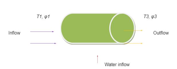
A mathematical model based on the principles of physics with the assumption that the fogging is adiabatic, is related to the expression, mw (hv3 – hw2) = ma (ha1 – ha3) + ω1 ma (hv1 – hv3). An adiabatic relation draws on the fact that the total amount of energy gained by the sprayed air is cancelled by the amount of energy lost by dry air under ideal conditions therefore establishing an energy equilibrium energy transfer condition. In this relation, the mass transfer of the cooling water is mw whose enthalpy is hw2. On the other hand, (ha3 – ha1) provides a relation on the enthalpy of dry air whereas the relation (hv1 – hv3) being the enthalpy due to the cooling water. In the equation, ω1 provides a value of the humidity ration that can also be obtained from the mathematical relation; ω1= (0.622 pv)/ (p1-p2). pv is the pressure that is achieved partially and p1 and p 2 are pressures due to water vapor and the atmosphere respectively (Air Quality Data., 1978).
According the laws of physics, mass can neither be created nor destroyed and based on the law of mass conservation, the amount of sprayed water at the inlet is equivalent to the mass of water at any specific point along the turbine, assuming the rate of mass transfer is constant for this case. However, under practical conditions, the rate of mass transfer may drastically vary along the turbine. The relation can be modeled mathematically as follows; mw = (ω3 – ω1) ma. It is important to note that the relation is defined by a variable of the humidity ration of the air after it has been cooled. In addition to that, it is possible to calculate the partial pressures based on the relations mathematically illustrated below;
pv1 = φ1 Psat1 and pv3 = φ3 Psat3.
Noteworthy are the variables in the equations where φ1 is the relative humidity in the mathematical model while the rest of the variables are the partial pressures that are achieved during the cooling of the mass flow. In addition to that, in the mathematical relation, Psat1 and Psat3 represent the pressures that are attained and defined at temperatures T1 and T2. As mentioned above, the modeling is assumed to be ideal, therefore pressure losses are assumed not to have occurred during the process. Hence, it is assumed that pressure P1 is similar to pressure P2. However, it is important to use a computer to get a number of comparative values with varying temperature ranges as mentioned elsewhere. It is however, important to determine the power performance of a turbine and the heat rating of the turbine after the above cooling has been achieved. That can be modeled based on the Power-Augmentation Sub-model discussed below (Boonnasa, Muangnapoh & Namprakai, 2006)
Powers-Augmentation Sub-model
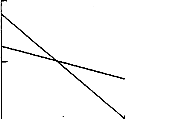
A turbine’s performance characteristics as demonstrated by Brooks (n.d)’s illustration of the performance curves shown below are a good pointer to the two variables of heat and power discussed above. A typical example of a turbine under consideration is the ABB GT13 Gas-Turbine. As illustrated in the diagram below, the power output of the turbine under consideration and the heat rate attained by the inflow mass’s air temperature, T, is calculated from the mathematical relations; (1) PO = ץPos, and (2) HR = HRs/µ. The variables, POs and HRs, represent the power output of the turbine and the temperature attained by the inflow mass respectively. For the turbine under consideration, the temperature of attained is estimated to be 15.6º C, being the standard temperature T mentioned above. The constant values used in the equations, the relative thermal efficiency of the system (µ) and the relative power of the system (γ) can be calculated based on the characteristics of the performance curves illustrated below (Air Quality Data., 1978) and (Dunn, n.d).
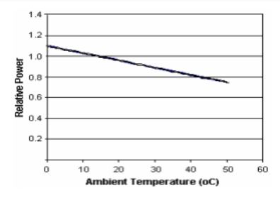
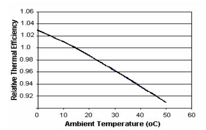
Deducing from the above graphs, the values of (µ) and (γ) can be calculated from the above graphs as demonstrated here, γ = 1.1007953 – 0.0068486514T – 9.6865641T² /10 pow7 from fig 1 and η = 1.0276476– 0.0018092128T – 1.105712T²/10 pow5 from fig 2. In addition to the above mathematical models, it is important to briefly provide mathematical models for conducting a cost benefit analysis of the fog-cooling strategy due to the cost benefits gained to justify the implementation or integration of the fog-cooling system into the inlet of a turbine (Nabati, Soltani, Hosseini & Ameri, 2003).
It has been demonstrated that fog-cooling can attract revenue that can be calculated based on an hourly basis from the relation, RMe = (PO3 – PO1) Ce. In this relation, Ce is based on the cost of energy to the customer and
PO3 and PO1 are respective values of power output when the system is subjected to cooling and when it is not subjected to cooling respectively. On the other hand, the hourly rate at which fuel can be saved is based on the following relation, RMf = PO3 (HR1 – HR3) Cf. From the mathematical relation, HR1 and HR3, are values of the heat rates that are calculated or obtained based on the ambient temperature (T1), and the temperature attained by the fog-cooled inflow mass (T3).
Analytically it is important for engineers to verify any model as it has practical implications on the performance of any specific turbine. Comparative studies have shown the importance of manufacturers of specific turbines to provide data on the performance of the turbines they have manufactured. These values can are critical in evaluating the above models for obtaining rough estimate data on various performance issues. A critical analysis, however, show that the mathematical derived above provide good estimates of the performance of different types of turbines with minor deviations from the actual values due to design and manufacturing issues (Air Quality Data., 1978.
It is important, therefore, for manufacturers and user of fog cooled turbines to note that the models can provide estimate values on the effect of cooling on the performance of a gas turbine when subjected to cooling at the inlet. However, it is important for the models to be specifically tailored to specific turbines due to variations in design and manufacturing issues and operating conditions (Air Quality Data., 1978).
Gas Turbine Thermodynamics
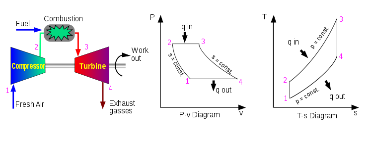
It is of critical importance to understand the thermal dynamic cycles and principles upon which gas turbines operate. Principally, the cycle is known as the Brayton cycle (Lane, n.d). The Brayton cycle is defined by two key parameters, the ration between the pressure in the turbine and the temperature at which firing takes place. In an argument presented by Javadi (n.d), in a typical environment, the pressure ratio is characterized by two pressure points expressed as a ratio of the discharge pressure of the compressor and the pressure at the inlet. The discussion is illustrated in the diagrams below for a typical turbine (Lane, n.d).
Ameri, Hejazi and Montaser (2005) theoretically model the Brayton cycles as discussed above. The impact of the parameters considered in the process play a critical role in determining the outcome of the calculations and other turbine performance issues. However, it is important to consider both practical and ideal situations under which the analysis below is conducted. One of the critical considerations is that the flow mass is air throught the analysis, the air used in the process behaves perfectly, the flow of fuel and its effect is constant throughout the Brayton cycle, the compressor and the turbine are both 100 % efficient, there are no pressure losses incurred during the inflow of the air mass, during the combustion process, and during the exit of the gases (Punwani, Pierson, Bagley & Ryan, 2001). In addition to that, the turbine is assumed to be in a state where it is not cooled. It has been and will be demonstrated below that the thermal efficiency of the Brayton cycle relies on the pressure ratio attained in the turbine (Air Quality Data., 1978).
Theoretically, the Brayton cycle is principally based on an isentropic cycle, the isobaric process, and the adiabatic processes. The cycle is defined by compressions, addition of heat into the inflow mass, expansion of the inflow and outflow mass, and the rejection of heat in the whole process. In addition to that, the Brayton cycle can ideally be calculated based on the mathematical relation, µ=1=T1/T2=1-(P1/P2) ץ-1)/ץ
Theoretically, the firing temperature is reached when the highest value for the temperature has been recorded. In addition to that, a comparison of two approaches as illustrated below indicates that the firing temperature causes a rise in the value of the temperature that is achieved in the process under the Brayton cycle.
Modeling of the open turbine cycle
Based on the Brayton cycle, it is important to conduct an analysis of the cycle. Theoretically, the model is a close loop based on standard considerations of an ideal behavior of the gas in the model. It is assumed that the compression of the gas involved in the process and its expansion remains constant. The whole Brayton cycle is an aggregate of four processes that are designated as internally irreversible. The whole of the four parametric considerations and heat considerations fall into the isentropic compression process in the turbine, an increment of heat at a constant rate, an expansion in the turbine that is isentropic, and the injection of constant pressure into the turbine (Ameri, Hejazi & Montaser, 2005). It is important to note that gas turbines influence a large amount of mass flow through the basic cycles at tremendous velocities. It has been demonstrated that the movements are within the gas turbines are smooth for the greater percentage of the motion of a gas turbine. That calls for an accurate and balanced design of the turbine blades to minimize and essentially do away with any potential to be damaged in the operational process. The air standards are theoretically taken to be adiabatic processes where a balance in pressure is achieved throughout the system as mentioned elsewhere. In addition to that, the irreversible process that is internally considered for the process is a thermodynamic condition in which specific operating temperatures of a gas turbine can be achieved with the overall effect of reversing the whole Brayton cycle with the aggregate effect of improving the efficiency of a turbine in relation to a state of equilibrium that can be achieved in the process. As illustrated in the above diagrams (fig 3), the Brayton cycles are clearly demonstrated. It is assumed that a steady flow is achieved in the process with the objective analyzing the whole cycle based on the steady flow state (Krulls & Lastella, n.d).
In the model Ameri, Hejazi and Montaser (2005) confirm that the flow of mass within the system makes the whole system gain energy equilibrium state per unit mass based on the following expression, (qin-q0ut) + (win-wout) =hexit-hin. Further analysis leads to the Brayton equation as stated below:
ηth, Brayton=1-1/(k-1)rp*k, where rp=p2/p1 (k, the ration used as a specific value).
It can therefore, be analogously deduced that the specific heat ratio and the ratio of the pressure of a gas determine the thermal efficiency if the Brayton cycle. It can be noted that the thermal efficiency of a turbine appreciates as the both parameters mentioned above increase (Dunn, n.d).
Ameri and Hejazi (2004) analytical views of the T-s and P-v diagrams illustrated above indicate that the specific heat capacity of the materials used in the design and construction of the turbine have been assumed to be constant. However, based on practical analysis of the behavior of the specific heat capacity of a material with rising temperature, it has been shown that the specific heat capacity varies with varying temperatures. Ameri and Hejazi (2004) observe that changes in the specific heat capacity have a strong influence on the behavior of a turbine and its power production efficiency. However, it worth noting that the temperature of the inflow mass increases at the outlet and is low at the inlet, therefore influencing the Brayton to a minimal extent. However, it has been demonstrated that the Brayton cycle calculations sometimes differ from practical values by a given margin. This can be calculated based on adiabatic considerations in the design and comparison process (Ameri & Hejazi, 2004).
Thermodynamic analysis
A thermodynamic analysis of the whole system leads to a critical evaluation of the Brayton cycle based on the parameters that influence the whole cycle as illustrated below.
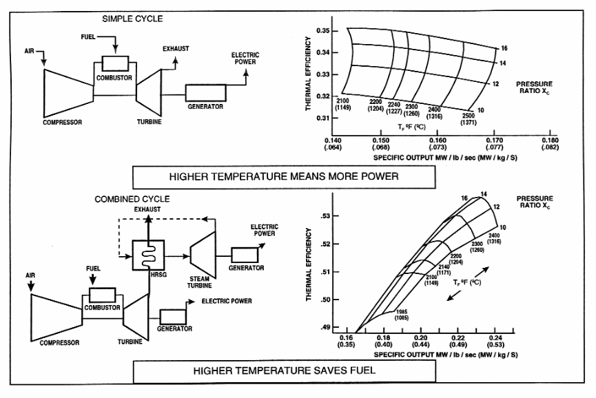
Johnson (1994) illustrates that increasing the firing temperature at which firing occurs varies the efficiency of the turbine in relation to the power output and the respective pressure ratios. However, certain factors influence the design of a turbine. It has been demonstrated that the rate of mass flow and the output per unit volume determines the size of the turbine. A smaller design indicates that when the output per unit volume is high, the size of the turbine decreases. In addition to that, the thermal efficiency of a turbine directly impacts on the fuel efficiency and power output from a turbine. Based on the above diagram, pressure ratios vary between different points in the whole cycle (Johnson, 1994). One important point in the design is that as higher pressure ratios are attained, there is a proportional rise in the efficiency and performance of a turbine. However, it can be demonstrated that the efficiency of a turbine are strongly related to the firing temperature. In addition to that, specific pressure ratios lead to optimal output as variations in output efficacy vary with temperatures (Alhazmy & Najjar, 2004).
It can be deduced from the above diagram that when the firing temperature appreciates, the power output increases at specific pressure ratios. However, it is important to consider in the design, the operating temperature the components of the turbine, thereby leading to a slight depreciation in performance (Chappell, 1973).
On the other hand, a critical consideration of a combined cycle application as illustrated in the above diagram indicates that when pressures appreciate, there is a slight effect on the efficiency of a turbine with a corresponding rise in temperature. It can also be analyzed from the above diagram that as the ratio of pressure increases, there is a penalty on the specific power. Specific power registers a decrease under such an environment. On the other hand, it can be deduced that thermal efficiency under these conditions increase when the firing temperature appreciates. It can be demonstrated that for both cycles, the cycle parameters for both cycles do not optimize efficiency under similar conditions (Alhazmy & Najjar, 2004).
One can note from the above curves that high pressure ratios result in efficient simple cycles. On the other hand, modest pressure rations lead to combined cycle efficiency with firing temperatures being relatively higher. it is therefore important when selecting specific turbines with specific cycles to base the selection on the above factors. Based on the above comparisons, it is important to consider a brief discussion of a combined cycle gas turbine below (Alhazmy & Najjar, 2004).
Combined cycle
Theoretical estimates indicate that a gas turbine that uses simple cycle has the ability to obtain a 30 % to 40 % conversion rate of the energy obtained from the input fuel into the output torque. It is only up to 2% percent of the energy that is lost into the exhaust in the process. On the other hand, a combined cycle, defined by a combination of gas turbines and recovery systems for the heat generated by these turbines, optimizes the heat-to-process. Other design and engineering considerations optimize the performance of a gas turbine based on the requirement specification in the application environment (Anderson & Neaman, n.d). However, it is important to understand the factors that influence the performance of a turbine as discussed below.
Factors Affecting Gas Turbine Performance
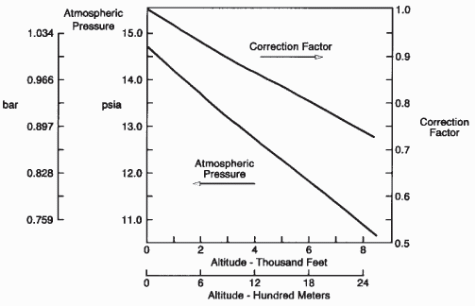
One of the key influencing factors in the performance of a turbine is the temperature of the air and the elevation of the turbine. It is worth noting that besides engineering consideration in the design of a turbine and other parametric issues discussed in the paper and ambient temperatures already discussed above, elevation is critical. These factors are specific to a specific turbine. It has been demonstrated that the elevation of a turbine influences the density of the air mass. The density is one of the critical elements in determining the performance of a turbine. It is therefore important for a correction to be done on a turbine specifically targeting its orientation and the resulting influence on the performance of a turbine. The standard correctional approach for the performance and elevation of a turbine is illustrated in the figure below (Ameri, Hejazi & Montaser, 2005).

From the above discussion, varying the ambient humidity has an effect on the power output and the performance of a turbine. It is clear from a number of experiments and practical data that the density of humid air is lower than dry air. That has an overall effect on the heat rate that translates to the performance of a turbine (Bradury, Hancock & Lewis, 1963). That is also in relation to the increasing size of turbines and the demands for energy efficiency placed on them. In addition to that, it is important to consider the treatment of inlet air to optimize the efficiency and the span of the turbine in question as discussed in the next section.
Treatment of Inlet Air Gas Turbine
It is an important requirement to treat the intake air to optimize the performance of a turbine when operating under different climatic condition particularly in this case hot climates. It is common for gas turbines to ingest a big amount of foreign particles and any other matter into the inlet while being operational. Zadpoor and Golshan ( 2006) note that in the process, potential hazards are bound to impair the efficiency if a turbine by modifying the chemical and mechanical properties of the turbine construction materials. Potential problems range from the effect of solid particles and corrosive fluids. These substances’ overall result in fouling, erosion of the compressor blades and other mechanical components, and general corrosion as already mentioned above (Bradury, Hancock & Lewis, 1963). It is important to remember that in hot climates, an evaporative cooler or a fog cooling strategy can be used to reduce the temperature of the inflow mass. For such reasons therefore, it is critically vital for any engineer considering the effect of cooling on the performance of a turbine to equally consider the effect of filtering the incident air with an overall impact on the performance of a turbine in addition of the cooling effect as argued by (Tatge, Gordon & Conkey, n.d).
Tatge, Gordon and Conkey (n.d) note that a number of filtration approaches are used in the process, but argue that is also important to consider in this discussion it the need for filtration of the incident gas by looking at the effects of corrosion, fouling effects and other mechanical damages to justify the need for filtration. One of the effects is erosion (Dai & Sumathy, 2002).
Erosion
Abrasive materials have the ability to score the surface blades of the axial compressor and other paths taken by the hot gas these materials come across. These particles can be sand or any other hard materials (Dai & Sumathy, 2002).
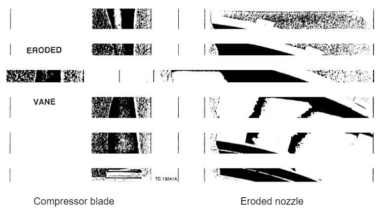
A keen analysis of the condition reveals that these particles come into contact with the compressor blades. In the process, they cut away pieces of metal of the compressor blades ultimately causing their corrosion (Bradury, Hancock & Lewis, 1963). The cutting rate is directly related to the impingement velocity of the particles, the modifying effect of temperature on the abrasive properties of the turbine blade materials, and rate at which the particles impinge on the surface of the blades and other materials. In addition to that, the impingement angle of the incident particle on the compressor blade and the mechanical properties of the scoring material combine to determine the nature of the wear produced on the material. It is, therefore, important to practically view the effect of wear on an eroded compressor blade and a nozzle in the first stage of the turbine system as illustrated below.
Fouling
Fouling is another effect that impacts on the performance of a turbine. It has been shown that fouling can cause severe penalties on the efficiency of a turbine, impairing the performance by a whole 20 percent. It is worth noting that the performance of a turbine largely depends on the smoothness of the rotating parts and the stationary parts of surface of compressor blades. Both theoretically and practically, it is impossible to form a mathematical model to determine or quantify the rate at which fouling occurs in a turbine because the influencing variables such as the properties of the sticking materials among other variables are difficult to determine (Bradury, Hancock & Lewis, 1963). However, it can be demonstrated that filtration largely removes a considerable amount of materials that cause fouling. Moreover, it is worth noting that filtration can not remove vapors and other related chemicals that may also have a corrosive effect on the compressor materials. However, due to technological advances, new approaches of removing the adhesive substances have been implemented. These materials are worth mentioning briefly (Dai & Sumathy, 2002).
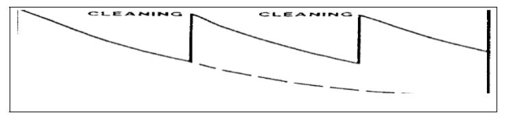
One of the approaches is using cleaning materials that have a mild abrasive effect on the material being cleaned. However, a number of studies do not agree to the use of this approach. Research has shown that these materials have the overall effect of removing and at times completely damaging coatings of the compressor blades and altering the overall look of the surface finish of the blades. For that reason, it is not feasible to use this mechanical approach to clean compressor blades (Bradury, Hancock & Lewis, 1963). However, further studies indicate that the use of ash free detergents has had a desirable effect in cleaning surfaces of compressor blades. The whole approach involves forcing the cleaning detergent into the compressor blade at cranking speeds, commonly designated as an offline technique. The effects are demonstrated in the diagram below. However, the extent to the corrosion effect is discussed below (Bradury, Hancock & Lewis, 1963).
Corrosion of the Compressor
One key element to consider is the corrosion of compressor blades in relation to the performance of a turbine. Deposits such as sea salt are among the chemical substances that lead to the corrosion of compressor blades. In addition to that, the potential for pitting in compressor blades adds to the worry that is caused on the blades (Bradury, Hancock & Lewis, 1963). Pitting leads to local stress on the compressor blades, roughens the blades, and reduces the ability of the blades to withstand fatigue. However, coatings and filtration have proved valuable in preserving the chemical and to some extent mechanical degradations of the compressor blades and other parts that come into contact with the flowing mass. However, it is critical to consider the overall effect of the combination of hot gases with some chemicals as discussed below (Randles, & Ansari, n.d).
Hot-section corrosion
Punwani, Pierson, Bagley and Ryan (2001) note that when filtration of the inflow is inefficient, some metals and other chemicals find their way into the turbine and as combustion temperatures are high, causes these materials to react with chemicals such as sulphur causing the surface coating to be degraded and consequently wear out. Typical sources of these chemicals are in the fogging systems or in fuels among other sources. However, limits for these materials can be established upon vigorous examinations of the operating conditions of the turbine and turbine blades and the fuels (Dai, & Sumathy, 2002).
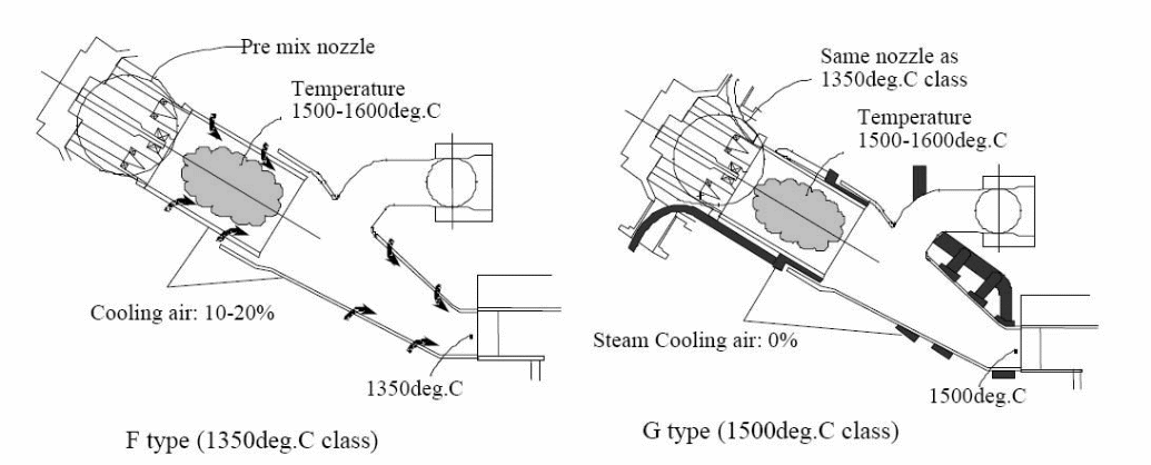
On the other hand, the flow of air for the purpose of cooling a turbine specifically for the combustion liner and other air flow ducts is necessary to maximize the efficiency of a turbine in the process of power production. However, it can be noted that during the ingestion of air flow, contaminations are likely to be in the ingested air (Toba, 1965). On prolonged flow of the cooling air through the gas cooling ducts, the contaminants may accumulate with time and eventually lead to the restriction of the air cooling abilities with the eventual results of impairing the overall performance of the turbine due to the heat and mass flow restrictions experienced by the blocking of the contaminants (Bradury, Hancock & Lewis, 1963). It is possible, therefore, for the heat trapped within the ducts and the housing of the compressor to rise to a critical value and cause cracking of the compressor system. Prevalence of this effect has especially been observed with machines designs of advanced technologies particularly the F machines. In addition to that, an environment with high concentrations of coal is especially dangerous for such machines as coal has a very high tendency to sinter (Dai, & Sumathy, 2002).
Environmental considerations
Engineers know well that ambient air is always susceptible to contaminations by solids, gases and even at times, liquids. However, further research clearly indicates that solids present the most potential risk to of damaging a turbine and the compressor turbines blades. One of the solids that affect the efficiency of a turbine is the flow of dust into the turbine. An aggregate amount of dust ingested into the inlet of a turbine is precisely dependent on the inflow mass, the inflow rate, and the total firing time (Tatge, Gordon & Conkey, n.d).
Statistical variations and data of dust particles particularly in hot countries show high concentrations of ducts in the air at specific periods and environmental disturbances. This is demonstrated in the figures below.
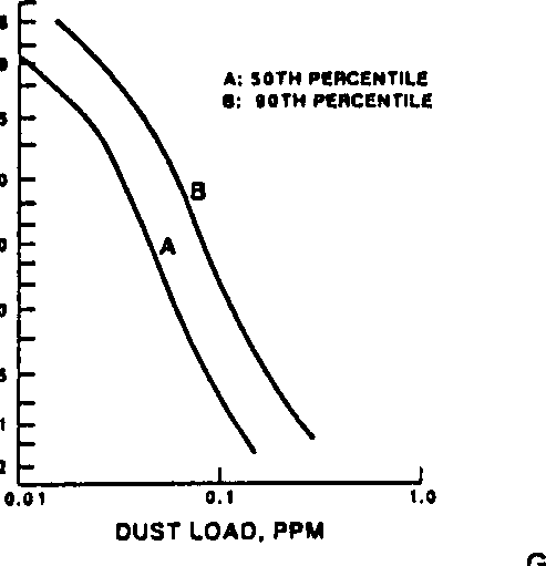
High efficiency filters
Fig 1 above indicates the variation of dust in hot areas and dusty areas with varying concentrations. On the other hand, fig 2 shows the concentration of dust in the air in relation to the orientation of a gas turbine. Tatge, Gordon and Conkey (n.d) reinforce that fact that dust concentrations in hot regions particularly deserts have the possibility of reaching very high concentrations in a very short or limited time span. Based on Stroke’s law, a valid argument shows that large particles nay become airborne in desert areas due to the force of the wind, gradually settling and leaving the finer particles being airborne for longer periods than the heavier and large particles. Therefore at lower elevations, dust particles tend to have a higher concentration than at higher levels. It therefore shows that elevations have an impact on the overall performance of a turbine based on the position of a turbine in relation to its orientation from the ground. It is valid to argue, therefore, that the orientation of a turbine and the place it is situated affects the level of the efficiency and the protection that can be afforded for a turbine in relation to contaminants and other ingestions (Tatge, Gordon, & Conkey, n.d).
An idea of the corrosive effects of dust particles particularly those that are constitute potassium and red sodium can be argue from the impact of their size inn relation to other dust particles. Despite that fact, it is clearly demonstrable that different regions have different dust particles with different chemical compositions. In desert regions, dust particles are very corrosive. Typical values indicate that sodium and potassium form as much as 5% of the total weight and composition of dust particles in this region. Based on these considerations, the need for filtration is very important. In addition to that, the need for high efficiency filtering is important in determining the efficiency of a turbine (Tatge, Gordon & Conkey, n.d).
Tatge, Gordon and Conkey (n.d) argue that a typical high efficiency filter is important as one of the measures of ensuring clean ingestions with the overall efficiency being improved besides improving the protective levels of turbine blades and other components that the inflow air comes into contact with. The typical efficiency of a high efficiency filter is influenced by the collection efficiency of the materials used in the design and construction of a filter. A typical design of a high efficiency filter is made of fiber glass. They take the shape of a panel or rectangular filter with specific filtration media used in the design. Notably, high efficiency filters work by trapping dust and other contaminants within the body of the media. These filters are designed to accommodate a surface loading media. The dust particles gather at the surface of the media used for trapping the contaminants. However, accumulating dust particles enhance the collection efficiency of the filter with time (Tatge, Gordon & Conkey, n.d). However, the surface loading properties of the filter determine the efficiency of the filter and the gradual dislodging of particles from the surface of the body. Another critical factor that influences the efficiency of a filter is the sealing applied on the joints of a filter. Different sealing fabrications can be achieved by different sealing mechanisms. Different filter designs provide different efficiencies. Preferably, cylindrical filters with higher mating surfaces provide higher filtration efficiencies than rectangular filters with smaller interaction surfaces (Tatge, Gordon & Conkey, n.d).
Recommendations for inlet gas filters
To provide adequate protection for a gas turbine, hence improving its efficiency in the long term, it is important to have solid knowledge of the behavior of the quality of ambient air It is important when selecting an appropriate approach to cleaning incident air to establish a string trade-off based on initial cost of a turbine and the filtration components, maintenance costs that are incurred in ensuring the efficient supply of filtered air and the general maintenance of a gas turbine, and the general performance or output from the specified gas turbine (Arrieta & Lora, n.d). The following recommendation is based on heavy duty gas turbines specifically tailored for desert conditions (Tatge, Gordon & Conkey, n.d). The following table indicates specific approaches used to classify the quality of ambient air. In addition to that, specific considerations such as future land use and other land use issues before settling at final options are important (Toba, 1965).
Recommended Filtration approaches. By Shah, 1978
It is clearly illustrated the approach and type of filter to adopt for a specific region. In addition to the considerations for special filters for special conditions, the filtration is also enhanced by incorporating into the design of a filter, insect screens. It is also important to provide weather hood protections for turbines. Besides that, turbines operating under hot conditions provide additional challenges in the lifespan of filters as heavy loads and usage are experienced for filters used under these conditions. Zadpoor and Golshan ( 2006) analytically argue that, self cleaning filters are recommended under desert conditions to optimize the working efficiency of a turbine with minimal need to shut it down when the filtration of inflow mass is most critical. Else, contingency supplies of spare filters should apply under such circumstances, a situation which may be ineffective in terms of procurement costs incurred. It is important also to note that the maintenance of a filtering system should be scheduled to be as regular as the maintenance of the turbine and the general maintenance of the whole systems in general. Having considered a length filtration and general requirements for filtration, it is important to consider evaporative filtration as a prelude to a comparative study of evaporative cooling and fog-cooling techniques as practical techniques in enhancing the efficiency of a turbine (Zadpoor & Golshan, 2006).
Evaporative Cooling
This approach is idealized on the fact that lowers temperatures can be achieved by using evaporating water at the inlet of a turbine to reduce the inflow air temperature to a desired level. The technique is widely viewed as being cost effective and widely used in the cooling of air at the inlet of gas turbine with the aim of improving or enhancing the overall performance of a turbine. The technique relies on two methods to achieve the cooling objective. One of the approaches is to use a large wetted surface positioned in the inside of the compartment for the inflow gas. On the other hand, it is commonly agreed that fogging is another evaporative cooling approach as discussed above for comparisons. However, this section is focused at evaporative cooling that takes advantage of positioning the cooling agent, in this case, water, at the inside of the inlet of the intake region of a turbine.
Practical considerations point out that the approach is cost effective based on a number of theoretical and practical principles. A solid knowledge of the theory behind the evaporative cooling theory is important to understand the whole concept behind the theory to afford comparing evaporative cooling and fogging system for typical applications as discussed below (Chaker, Meher-Homji, Mee, 2002).
The Theory of Evaporative Cooling
The theory is based on the principle that the temperature of air can be reduced when it flows through evaporating air. However, the whole process requires expenditure of energy to produce desirable results. It can be demonstrated practically the source of energy in this cycle is the flowing mass of air. The overall effect is a cooler air resulting in a rise in density if the flowing mass of air at the intake point of the turbine. Theoretical estimates indicate that the lowest temperature that can be achieved in this case is equivalent to the ambient wet-bulb temperature under ideal conditions. However, deviations from practical estimates have been widely noted. It is therefore difficulty to achieve such a level of cooling based on the theory (Arrieta & Lora, n.d).
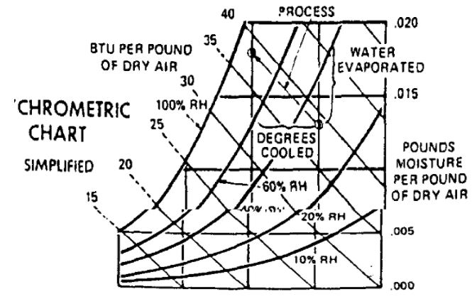
Theoretically, the cooling effect relies heavily on design and surface area factors. In addition to that, the atmospheric conditions play a critical role in determining the efficiency of the technique. Other influencing factors are the time of contact with the surface and the air being cooled. An effective design should provide optimal cooling results due to an efficient exposure and distribution of the cooling elements. Therefore, variables such as wet and dry bulb temperatures, the conditions under which the inflow mass exist from the system, and the overall state under which the air mass flows into the cooler. Therefore, the drop in temperature that is achieved under such conditions, assuming that the cooler is 85 percent efficient, temperature drop = T1-T2, where are T1 is the initial conditions and T2 the final conditions. The behavior is illustrated in the psychometric chart illustrated below. The chart is draw such that the horizontal axis represents dry bulb temperature, while the lines indicate various conditions that are variables to determining the efficiency of the cooling approach.
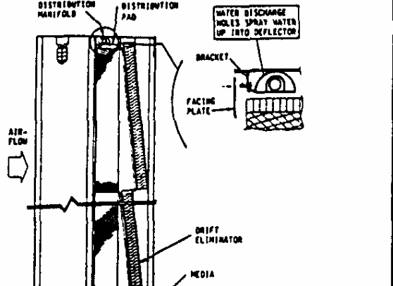
The typical procedure includes pumping water from the bottom of a reservoir which flow to the top for distribution at the head of the system. The header incorporates media blocks that are made of interconnected layers particularly in the internal section of the design made of corrugated materials. The layers are divided into two compartments, one for water and the other compartment is for air. The aim of separating the flow is to minimize the carry-over effect. The interconnections and channels cause the water flow to diffuse into the surrounding areas while the level of water is constantly maintained through valves that are incorporated into the design. Below is an illustration of a typical design of an evaporative cooler. The design uses gravitational force to make the flow of water possible through the passages spreading throughout the media as illustrated in the diagram. It is possible to attain different ambient temperatures using preset functions to achieve different temperature ranges. However, evaporations have to be allowed to occur at specified temperatures to avoid an icing effect (Arrieta & Lora, n.d).
The system is designed to deactivate itself in the event of the dry bulb temperature indicating the possibility of reducing drastically close to the icing temperature. In that case, the whole system should be drained to avert possible damages due to icing (Arrieta & Lora, n.d).
As discussed above, optimal efficiency is achieved by organizing the interconnected layers angles of 15º and 45º irregularly as illustrated below.
In order to model the above environment mathematically, a number of boundary conditions have to be considered here. Key considerations include the fact that isothermal conditions can be achieved and can be factored in the calculations specifically on the channel and slip walls and temperatures are uniform at the inlet of the turbine and the inflow velocity is constant. On the other hand, it is assumed that end conditions are constant at the outlet, where the velocity and the temperatures at that point are developed to the maximum levels achievable, symmetrical conditions are adopted for use at the lower and upper boundary conditions, and pressure boundary conditions are taken to assume Neumann boundary conditions. These translates to the equation, a0+ b0 cos(woZ) _ Y ¼ =0.
Analytically, therefore, the depth of the media and the velocity of the inflow air mass are critical in influencing the efficiency of the evaporative cooler and ultimately the efficiency of the turbine and its lifespan.
Evaporative coolers are best suited for arid or desert conditions. One unique characteristic with water in desert areas is that deposits are common prevalence the water. Therefore, the accumulating effect of minerals in the water is experienced in the process of adding up water solely for toping up purposes. The aggregate effect of these chemicals is to reduce the evaporative efficiency of the system. It is therefore necessary to determine the chemical composition of the water that is used in the evaporative system. It calls upon a standard laboratory analysis of the water to determine its safe use in the evaporative system. These outcomes are based on the operational outcomes of the evaporative cooler as discussed below.
Analytically, different problems have been experienced when using the evaporative method. Among the shortcomings included water entrainment, among other problems. However solutions to fix these problems included installing blankets in the cooling path among others.
Having discussed in detail about evaporative coolers, it is now possible to discuss in detail about the differences between fogging system and the evaporative system. Keen differences have been noted in terms of operability and applications as discussed below.
Comparison of Evaporator System and Fogging System
The evaporator system has been known to achieve an 85 % and 90 % humidity cooling efficiency as compared with fogging systems. This is achieved by specific media types that are used in such systems. On the other hand, it has been demonstrated practically that fogging systems achieve to near or completely 100% humidity levels. That places demands for uses of the system to ensure the process is controlled at all stages of the cooling process. Typical designs of fogging systems achieve optimal cooling capabilities with the objective of using all the cooling potential in climatic regions that are extremely dry. In addition to that, fogging systems are driven by parametric issues such as the size of the fog droplet used in the cooling process for efficiency. It is also important to establish and use available climate data when using fogging systems to carefully evaluate the best technique to apply when using the fogging system.
Another difference between the tow techniques is that evaporative cooling systems tend to create pressure drops in the orating environment. On the other hand, fogging systems depend on pressure due to the fogging fluid. Evaporative coolers are therefore preferably used in areas of hit and dry weather where evaporations of the cooling water are achieved using minimal amounts of energy. On the other hand, fogging systems are best suited in environments where the base loads are achieved and where peak loads are also achievable for the systems being cooled. Evaporative cooling systems demand ducts to be very large to accommodate the large amount of gas inflow since the process is slow. On the other hand, fogging systems are faster since they rely on the fluid pressure and the pressure of the droplets of the spraying nozzle.
Experimental findings indicate that evaporative cooling relies heavily on difference in temperature and once specific temperature limit has been achieved, it is not possible to improve the performance beyond that temperature and ambient condition. In addition to that, evaporative cooling entirely relies on climate cooling as opposed to the fogging systems that relies on forced pressure. However, evaporative cooling has been found to be very efficient in an environment of dry weather conditions achieving optimal thermal efficiency improvements at 40º C with a relative humidity of 10 %.
However, evaporative cooling systems suffer from certain limitations. One limiting factor is the wet bulb temperature where additional humidity doe not influence the cooling effect any further.
Careful considerations indicate that the capital costs of evaporative systems are significantly lower than that of a fogging system. Practical and theoretical data estimates on the operational and maintenance costs of evaporative cooling systems. It has been demonstrated practically that evaporative cooling systems can operate on raw water without the need to demineralize the water that is used for cooling as is the case with fogging systems. Industry applications reveal that the time taken to install evaporative systems is much lower compared to the time required to install a fogging systems for industry use. It is further stressed that evaporative systems are characterized by their ability to provide series as an air washer and cleaner. However, as compared to fogging systems, the evaporative cooler has limited scalabilities and is critically influenced by defining characteristics of the wet properties of the installation site.
Both evaporative and fogging systems share some common characteristics. Their installation time is small, they have low maintenance costs. However, the performance of the gas turbine can be increased as compared to evaporative cooling where the efficiencies cannot be improved. On the other hand, fogging systems have limited capacity for improvements compared with evaporative cooling systems that are scalable, and are strongly influenced by the wet bulb of the site of installation. Typical industry comparison table is illustrated below between evaporative systems and fogging systems as a summary.
By Shah, 1978.
Conclusion
Gas turbine performance can be improved by adding a cooling system at the point of air intake. Different systems modeled under different operating conditions have been used. Specific systems such as the fogging technique have been used with different results. However, optimal efficiency can be achieved by a careful balance of parametric factors such as the temperature at the inlet of a turbine, the mechanical efficiency achieved by the gas generator, the critically optimal speeds that are attained by the gas turbine, the temperature of the exhaust gases, and the pressure at which the turbine compressor discharges gas as a direct variable of the rate at which fogging is applied at the inlet of the gas turbine. An effective fogging system’s cooling efficiency is largely influenced design constraints at the point of inlet and the design of the compressor to attain efficient wet-bulb temperature values. On the other hand, evaporative cooling, a widely used method in hot and dry climates, is idealized on the fact that lowers temperatures can be achieved by using evaporating water at the inlet of a turbine to reduce the inflow air temperature to a minimum level.
The latter system has received wide usage as it is viewed as cost effective and widely used in the cooling of air at the inlet of gas turbine with the aim of improving or enhancing the overall performance of a turbine. These systems depend on two approaches to achieve the cooling objective. One approach uses a large surface that is made wet and positioned in the inside of the turbine. In addition to that, a cost benefit analysis reinforces the idea of cooling a gas at the point of entry to reduce its density and consequently improve the overall performance as a cost benefit advantage. Mathematical models of the approaches and practical considerations indicate a number of benefits and demerits of each of the above systems in practical environments. Therefore, the choice of cooling system has to be thoroughly vetted against the operating environment, cost and maintenance operations, and the projected use of the turbine. Overall, the use of a fogging system at the inlet of a turbine to enhance or improve its performance is an engineering solution for upping the performance of a turbine.
Recommendations
Drawing from the above findings, it is vital that further research be conducted in specific areas such as researching more into the thermodynamics and kinetic energy of droplets in a fogging system by focusing on the effect of the inlet gas on the performance of the fogging system. In addition to that, computational models and simulations need to be used as tools for studying the shattering dynamics of fluid droplets focusing on their behavior with fogging systems, a comparative analysis of the behavior of nozzles in atomizing fluids, and the trajectories created by droplets when injection takes place. It is also important to study in detail about the agglomeration of fluid droplets, the nomenclature of fluid droplets during injection, the model under which droplets transfer energy is such systems, and the overall effects of forced convection of fluid droplets. More detailed comparative studies need also to be conducted for fogging systems and evaporative systems to identify the most feasible systems to use in specific situations. In addition to that, there is need to involve industrial manufacturers of these systems to provide a more informed bridge between theoretical and practical issues and applications of these systems.
Appendix
Data Sheet
Typical steam turbine for comparison with gas turbine
By Butterworth Heinemann, 1998
By Butterworth Heinemann, 1998
References
Air Quality Data., 1978. Annual Statistics, EPA-450/4-79-037, U.S. Environmental Protection Agency, Research Triangle Park, North Carolina.
Alhazmy, M. M, Najjar, Y.S.H. 2004. Augmentation of gas turbine performance using air coolers. Applied Thermal Engineering 24:415–29.
Ameri, M & Hejazi, S. H. 2004. The study of capacity enhancement of the Chabahar gas turbine installation using an absorption chiller. Applied Thermal Engineering;24:59–68.
Ameri, M., Hejazi, S.H & Montaser, K.2005. Performance and economic of the thermal energy storage systems to enhance the peaking capacity of the gas turbines. Applied Thermal Engineering 25:241–51.
Anderson, A.W & Neaman, R.G. n.d. Field Experience with Pulse-Jet Self-Cleaning Air Filtration on Gas Turbines in a Desert Environment, ASME Paper 82-GT-283.
Arrieta, R.P & Lora, E.S. n.d. Influence of ambient temperature on combined cycle power plant performance. Applied Energy. 2005;80:261–72.
Beshkani, A & Hosseini, R. 2006. Numerical modeling of rigid media evaporative cooler. Applied Thermal Engineering, 26:636–43.
Boonnasa, S., Muangnapoh, T & Namprakai, P. 2006. Performance improvement of the combined cycle power plant by intake air cooling using an absorption chiller. Energy, 31:2036–46.
Bradury, B.J. Hancock, P., & Lewis, H. 1963. The Corrosion of Nickel-Base in Gas Turbine and Boiler Atmospheres, Metallurgia, pp. 3-14.
Brooks, F J.n.d. GE Gas Turbine Performance Characteristics. Web.
Chaker, M., Meher-Homji, C.B., Mee, T., 2002. Inlet Fogging Of Gas Turbine Engines – Part A: Fog Droplet Thermodynamics, Heat Transfer and Practical Considerations. Web.
Chappell, M.S. 1973. Stationary Gas Turbine Icing Problems: The Icing Environment, National Research Council, Ottawa, Canada
Cortes, C & Willems, D. 2003. Gas turbine inlet air cooling techniques, an overview of current technologies, Power Gen, Las Vegas, Nevada
Dai, Y.J & Sumathy, K. 2002. Theoretical study on a cross-flow direct evaporative cooler using honeycomb papers as packing material. Applied Thermal Engineering, 22:1417–30.
Dunn, D.J. n.d. Applied Thermal Dynamics. Tutorial No.3 Gas Turbine Power Cycles. Web.
Fairman, L., 1962. Mechanism of Accelerated Oxidation by Vanadium-Containing Fuel Ash, Corrosion Science, Vol. 2 pp.293-296.
Grabe, W. and Chappell, M.S. 1974. Stationary Gas Turbine Icing Some Design Guidelines for Blowing Snow Environments, National Research Council, Ottawa, Canada.
Holman, J.P.1997. Heat transfer. 8th ed. McGraw Hill
Javadi, H. n.d. Thermodynamics laws, Entropy and CPH Theory. The General Science Journal. Azad University,Tehran,Iran. Web.
Johnson, R. S.1989. The theory and operation of evaporative coolers for industrial gas turbine installations. ASME Journal of Engineering for Gas Turbines and Power, 111(2):327–34.
Johnson, R. S. 1994. Set up and operation of a recirculating wetted rigid media evaporative cooler installed in a gas turbine combustion inlet air system. In: International gas turbine and aeroengine congress and exposition, The Hague, Netherlands.
Krulls, G.E. & Lastella, J. n.d. Gas Turbine Salt Ingestion Analysis.* ASME Paper 77GT20.
Lane, D. n.d. Brayton Cycle: The Ideal Cycle for Gas-Turbine Engines In Relation to Power Plants. Web.
Nabati, H., Soltani, M., Hosseini, R & Ameri, M. 2003. Technical and economic assessment of the inlet air cooling system application for power augmentation in the hot seasons for Ray power plant Fiat gas turbine units. In: Proceeding of 18th PSC conference, Tehran-Iran, vol. 2. p. 203–13.
Punwani, V., Pierson, T., Bagley, J. W & Ryan, W. A. 2001. A hybrid system for combustion turbine inlet air cooling at the Capine Clear Lake Cogeneration Plant in Pasadena. Texas, ASHRAE winter meeting, Atlanta.
Randles, R.H. & Ansari, F.n.d. Evaluation of the Peerless Mark 1 Spray Eliminator for Protection of Marine Gas Turbine Air Intakes, Naval Marine Wing Note No. 30/71, National Gas Turbine Establishment, Pyestock, Hams, England.
Shah, R.K. 1978. A correlation for laminar hydrodynamic length solutions for circular and noncircular ducts. Journal of Fluids Engineering, 100:177–9.
Tatge, R.B., Gordon, C.R & Conkey, R-S., n.d. Gas Turbine Inlet Air Filtration in Marine Environments-Part I: Marine Aerosols and Equipment for Their Control,” ASME Paper 8O-GT-174.
Tatge, RB., Gordon, C.R & Conkey, R.S. n.d. Gas Turbine Inlet Air Filtration in Marine Environments Part II: Commercial Experience and Recommended Practice,” ASME Paper 8@GT-175.
Technical specification of the project, design, manufacturing, and installation of media evaporative cooling system for 6 units of Fars combined cycle power plant. 2002. Fars regional electricity board project code:PMEBS01
Toba, Y, 1965. On the Giant SeaSalt Particles in the Atmosphere, Tellus, Vol. 17, NO. 1, pp. 131-145
Zadpoor, A. A & Golshan, A.H. 2006.Performance improvement of a gas turbine cycle by using a desiccant-based evaporative cooling system. Energy. 31:2652–64.