Introduction
Airplane flight data recorders are used in the collection, recording, and synthesis of data obtained from airplane sensors. The recorder is designed in such a way it often survives airplane accidents (Smith, 2007: 17). Depending on the age of a plane, the flight data recorders may include either an analog or a digital data acquisition unit, and a digital flight data recorder or a simple FDR (Baker, 2008: 12).
This is a device that has over the years, been installed on many planes, thereby enhancing aviation safety. Data collected from these devices is often useful in the investigation of plane accident causes. Data from this device has been used in design improvements for planes globally. For instance, engine high hours data obtained from FDR’s are critical in determination on when it is appropriate to replace the engine and hence reduces the possibility of failure. Understanding flight data recorders require a deeper in-look into their functions, uses, and technological changes in their development.
This paper attempts to answer some of the questions that one may have with regard to flight data recorders by assessing their functionality, their application to a real case accident, the parameters successfully measured in the past and currently. This assessment opens the readers view into a more realistic approach to the understanding of flight data recorders. Diagrams are provided where appropriate to illustrate its application. Additionally, a few parameters it reveals and their importance are discussed.
Discussion
Black boxes that record fight information are part of most modern-day aircrafts (the United States, Office of Aviation Safety, 2002: 51). Based on their data, events prior to an accident can be easily reconstructed in a bid to determine the cause of the accident. Radio transmissions and other cockpit sounds are recorded using cockpit voice recorders (CVR). Recorded information includes engine sounds and crew conversation among others. It additionally records various flight parameters. These parameters include altitudes, air speed, and fuel flow among others (Baker, 2008: 14).
Inch magnetic tapes were used in the olden times for data storage. This has however, changed with digital and memory chips being use in pace f the olden technology.
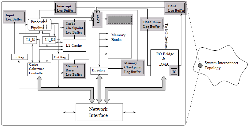
To secure them from damage, both are normally installed in the least crash prone zones of the plane, often the tail region. In cases of water accidents, the underwater beacons assist in the location of the recorders (United States, Office of Aviation Safety, 2002: 52). A pinger, which transmits signals at 37.5 KHz, is activated upon immersion into water. This process is assisted using a special receiver (Baker, 2008: 14). These measures are usually aimed at ensuring easy detection of the box and in some instances the plane when it goes missing. The diagram below illustrates a typical flight data recording system (Smith, 2007: 19).
The flight data recorders play a crucial role in the enhancement of aviation safety. As it has often been said, a mistake can only be avoided by understanding the vents that led to it and avoiding the same, this is also applicable in aviation. The FDR offers experts within the industry to reconstruct and hence develop a deeper understanding of cases of accidents hence avoid the same in future. It is however important to note that the time that this devices cease to operate determines how useful they are during post-accident investigations. The FDR’s are power dependant and often they cease to operate when the plane undergoes total power failure due to power loss of both engines (United States, Office of Aviation Safety, 2002: 57). Such occurrences greatly impair investigation efforts especially in instances where the crew and flight passengers do not live to tell the story.
In some accidents, the memory cable is often damaged, as was the case in American Airlines flight 587, an Airbus A300-600, but is replaceable to facilitate data reading (United States, Office of Aviation Safety, 2002: 58). The memory is often used by the investigative body’s laboratory for configurations meant to emulate the accident under investigation. Downloaded data from this memory is in binary vales (O’s and 1’s) and is therefore converted into readable engineering units e.g. feet, knots, degrees Celsius e.t.c. the actual conversion involves the use of computers and associated software.
In the QAN depressurization incident, a number of parameters were evaluated before drawing of a conclusion that the accident was a result of depressurization. The parameters recorded included vertical acceleration (g), pitch (deg), altitude pressure (longitudinal acceleration (g), latitude acceleration (g), headings (deg), airspeed (kts) and altitude radio (ft). See figure 2. Attached. However, it is important to note that there were also some other important parameters whose measurements would have been useful in assessing the circumstances that led to the aircraft’s accident. These include the filtered data records namely: rudder position, aileron position, and the horizontal stabilizer position.
Ailerons control surfaces joined to trailing edges aircraft fixed-wing. They control the aircraft in roll (Walters & Sumwalt, 2007: 34). Unwanted side effects n it often results in adverse yaw and is usually a result of drag difference on the wings. The resulting between up aileron and down aileron is undesirable and hence it is important to keep track of any changes with regard to the aileron. Such changes data could be useful in assessing the origin of a problem.
In detecting whether the accident was a pilot error might prove useful to have a track of the radar position at any one time. This is given the fact that it affects thrust and if pilots control mechanically in an undesirable manner in synchronization effect with thrust increase the result may be an accident. Changes in variable position of horizontal stabilizer simultaneously alter the pitch and setting of flaperon (Walters & Sumwalt, 2007: 37). Normally it is fixed and ahs a elevator that is hinged. Changes in its position could reflect possibly hidden problems that could have resulted in the plane crash. For instance in flight 261, the changes on horizontal stabilizer position was due to a jam in the jackscrew that was supposed to mode the whole stabilizer (United States, Office of Aviation Safety, 2002: 59).
Digital flight data recorders senses and records information in serial data format. The information received has sensed parameters and come in successive data frames (Smith, 2007: 17). The information is circulated in a first in first out sequence via a minor memory, which preserves the received data in a real time interval. The data is then compressed into smaller database inclusive of periodic slow interval samples and samples of intermediate exceedance, which are then, stored in the major memory for later retrieval (Smith, 2007: 17). Based on the CAO requirements, for a plane with maximum recording intervals of 0.5 seconds translates into a recording rate /time of 16. This is derived from the longitudinal acceleration equation.
Quick access recorders are also found in planes. Usually, they record the same data as FDR’s. The data acquisition units obtain and feed data to both QAR and FDR. The QAR’s unlike the FDR’s are however, light, cheap, durable, and easy to use. The vast advantages it presents in comparison to FDR’s has increasingly endeared it various plane designers. However, it s worth noting that most aircrafts have both installed. It is also important to state that event technologies are additionally incorporating video recording in flight recording technique. This s expected to assist future investigations through provisions of images of the actual patterns/sequence in which events leading to an accident transpired.
This will further enhance the roe played by these flight-recording tools in enhancing aviation safety. Needless to mention that in aviation industry, safety is top priority taking into consideration the gravity of accidents associated with it.
Event buttons are used to set markers for events as they occur.Usually the buttons are presents to signify the start of recording for events of interest during flight (Campbell, 2001: 64). They offer an avenue for recording specific data, which may prove of interest to investigators in case f accidents and even n the absence of accidents. At this point it is important to mention that flight data recorders do not only offer information for accident reviews but are also use n review of aircraft performance and hence making of possible to improve performance in case of deterioration. For instance, tracking changes engine power fluctuation and performance is useful in assessing and determining increased failure probability (Smith, 2007: 18).
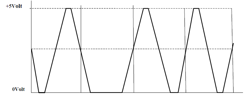
Appropriate response may then be taken early enough. Interpretation of analogue formatted data form flight data recorders is also an important step in analysis of aircraft crash. Fig. 3 is an example of an analogue presentation of data from the FDR’s. Its reflects voltage fluctuation by the aircraft during its flight period. There is a consistent change in voltage throughout the recording.
Conclusion
In conclusion, it will be important to note that advances in flight data recorded has seen breakthrough in solving of mysterious causes of plane accidents. While the area is still open to innovation as it still faces challenges, the milestones achieved over the years cannot be ignored. Currently, data flight records are able to register more than one thousand parameters during travel. Based on this, it is recommended that future technology embraces a more wholesome approach that ensures all flight data are accorded importance and hence recorded in case need arises.
References
Baker, D. (2008) Aircraft Certification Service. Washington DC.
Campbell, N. (2001) The Evolution of Flight Data Analysis, Australian Society of Air Safety Investigators conference. pp 56 – 86.
Smith, J. (2007) DFDR and CRV’s is in flight safety enhancement, Cape Town, Bloomville Publishers. pp 11 – 19.
United States, Office of Aviation Safety. (2002) Flight data recorder handbook for aviation accident investigations: a reference for Safety Board Staff, National Transportation Safety Board. pp 45 – 67.
Walters, J. M. & Sumwalt, R. L. (2007) Aircraft Accident Analysis: Final report, London, McGraw Hill. pp 23 -45.