Executive Summary
The demand for electricity in today’s world is on the rise. As a result, many technologies are being tested to come up with the most appropriate one to supplement the current electric power generation. Over the years, the use of pressurized water reactors has become common. The process is carried out in nuclear power stations. Radioactive fuel is used as a source of energy. The plants use three distinct water systems to generate electricity. The three are the primary, the secondary, and the condenser systems. Only the primary and the secondary systems play an active role in the functioning of the plant. The condenser system plays a passive role in that it only helps in cooling the feed water. Secondary and primary water systems share some similarities. For example, both are closed. As such, their contents are physically separated. The primary system cools the reactor fuel after it has undergone fission, which is a heat-generating process. The primary system carries the heat it has drawn from the reactor to the steam generator. Here, the primary and the secondary systems exchange heat. Water in the secondary system is superheated to produce steam. The steam is dried. It is then directed towards the main turbine. The turbine is under high pressure. From there, it is dried once again and reheated to boost its pressure. It is then directed towards the low-pressure turbines. The turbines are linked to a generator. Electricity generated from these nuclear plants is used in industrial and residential areas. It can also be used in naval vessels, such as warships and submarines. However, it is important to carefully monitor the plant to avoid accidents, which may be catastrophic.
Introduction
With demand for electricity on the rise across the world, countries have to come up with additional means of boosting their power production (Krepper 2013). Many alternatives are currently under trial in different nations. They include wind, solar, and hydroelectric stations. Even so, the use of steam to generate power has become popular, especially in developed countries. There are a lot of deliberations with regards to the best source of steam for power generation. Traditionally, heat sources, such as coal, were used for the purposes of heating water. However, with technological advancements, other sources of heat, such as nuclear reactors, are being used.
There are a number of commonly used nuclear power reactors. One of them is the Light Water Reactor (LWRs). Under this category, the Pressurised Water Reactor (PWR) is the most commonly used. PWR plants rely on nuclear fission to generate heat. Radioactive materials, usually uranium and plutonium, are used as fuel in the reactor (Lips 2005). The basic functioning of the PWRs involves the transfer of heat generated in the nuclear core to water.
It is important to note that PWR has three separate water systems. The three are primary, secondary, and condenser. In the first one, water is heated under very high temperatures. Heat is passed on to the water in the first system. The exchange takes place as the water circulates around the heads of the reactor vessels. Here, it acts as a coolant to moderate the heat generated (Krepper 2013). The water in the system comes in direct contact with uranium fuel. The temperatures in the first system are high. However, the water is not allowed to boil. To ensure this, it is kept under high pressure. It is important to note that the system is contained. Water is held within a piping loop. It is highly pressurized. It also passes a series of tubes. The piping is within the steam generator.
The tubes are held inside a second water system. Its main purpose is to generate steam. As a result, it is referred to as the steam-generating system. The heat from the first system is transferred to the second. In the secondary system, it is transformed to steam which is then pumped to the turbine chamber (Nakath, Schuster & Hurtado 2013). The second water system is also closed. As such, it does not come into contact with water from the other systems. The third water system is referred to as the condenser. It is used for the purpose of cooling the steam that escapes from the turbine chambers. The condensed water is returned into the steam generator and the cycle is recurring.
In this paper, the author seeks to explore the processes involved in the generation of power in PWRs. All aspects of PWR will be taken into consideration. The components of PWR plants will also be highlighted and their functions discussed. The advantages and disadvantages of the system will also be analyzed. The author will also look into the safety issues associated with the use of these plants. In conclusion, waste management will be discussed. Tables, graphs, pictures, and schemes will be used to illustrate the various aspects of PWR.
The Pressurised Water Reactor System
Overview
The setting up of nuclear power plants requires strict procedures to be followed. The plants are complex and are composed of many systems performing different functions. For the plant to be successful, it is important for these systems to be effective and efficient in performing their various functions (Krepper 2013). Two major systems play a major role in the production of electricity in the PWRs. The two are the primary and secondary systems. The two systems are linked together through the steam generator. Although water is used in both systems, it is important to note that their contents do not mix. Only heat is exchanged between the two systems but not water. There is a third one, which is also referred to as the condenser. It plays an important role in the recycling of water within the system. However, it does not directly impact on electricity generation.
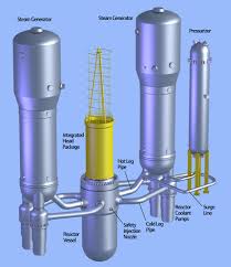
The diagram below illustrates the three different systems of PWR and their components:

The Primary System
The system is also commonly referred to as the reactor coolant. Its main role is to pass heat to the generator. The energy is generated from the reactor fuel. It also helps in the containment of any fission waste products that may escape from the fuel reactor. It consists of five major components which include the reactor vessel, the steam generator, the coolant pump, pressuriser, and connecting pipes (Madasamy et al. 2011). It is noted that the steam generator only acts as the site for heat transfer between the primary and the secondary systems. As such, the contents of the two systems never come into contact. The basic components of the system are interconnected by a series of piping. It is also tightly enclosed to avoid spilling its content. Since the system works under high pressure, great care should be taken to avoid any faults which could be catastrophic. The water in this compartment is also contaminated with radioactive products emanating from the fuel. As such, leakages within the system would expose individuals working in the plants to radiations. When such occurrences take place on a large scale, the effect is often catastrophic. To this end, radiations can be experienced over a wide area.
The major components of all PWR systems are similar. However, the arrangement of the components may vary from one plant to another (Madasamy et al. 2011). For example, it may have between 2 and 4 loops. The number of loops within a plant depends on the amount of power it is expected to generate.
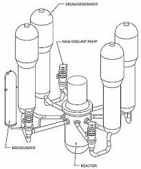
The two-loop PWR plant
The two-loop PWR plant is unique in that it has two steam generators. In addition, it has a pair of reactor coolant pumps. However, the plants have a single fuel reactor and pressuriser. Another major characteristic of the two-loop plants is the components of their reactor vessel. In most cases, it has 121 fuel assemblies (Lee et al. 2005). Each of these fuel assemblies is arranged in 14 x 14 arrays. They are 132 inches in diameter. The plants are considered to have a slightly lower power output compared to those with three and four-loops. On average, the installation produce 500 megawatts of power.
The diagram below is an illustration of the two-loop PWR plant’s major components and their arrangement:
The three-loop PWR plant
The three-loop PWR plant has three steam generators. It also has a total of three reactor coolant pumps and a single pressuriser. The PWR plants of this kind have 157 fuel assemblies. Some plants may have fuel assemblies are arranged in 15 x 15 arrays while others are17 x 17 (Krepper & Schaffrath 2013). The reactor vessels are also of a larger diameter compared to those used in the two-loop system. They are 156 and 159 inches. The reason behind this is that they accommodate more fuel assemblies which are required to provide additional heating. The power output of the installation varies. It ranges from 700 to slightly over 900 megawatts.
The diagram below is an illustration of the three-loop PWR plant’s major components and their arrangement:
The four-loop PWR plant
The four-loop PWR plant is the largest of the three systems. It has four steam generators. It also has a total of four reactor coolant pumps and a single pressuriser. Most plants that are of this kind use 193 fuel assemblies. They are all fitted in a reactor vessel that is 173 inches in diameter. The fuel assemblies are arranged in 17 x 17 arrays (Krepper & Schaffrath 2013). However, in rare cases, the 15 x 15 arrays may be used. The plants produce the highest amount of power among the three. On average, they produce between 950 and 1250 megawatts.
The diagram below is an illustration of the four-loop PWR plant’s major components and their arrangement:
Components of the primary system and their functions
Pressuriser
The pressuriser is also one of the basic components of the primary system. Its main role is to regulate the pressure of the system. In order to perform this function, it has four major components which include an electrical heater, a safety valve, and a pressuriser spray. It also contains a series of relief valves. The primary system works with steam and water. The two are in equal ratios. The main reason behind this is to prevent boiling. A deviation from this is quickly returned to norm. There are various sources of pressure variations within the system. One is an increase in temperature. A change in pressure is directly proportional to temperature (Hohne & Kliem 2007). As such, an increase in temperatures will automatically lead to a rise in pressure and vice versa.
The reactor coolant system is hooked to the pressuriser. The link is established through a surge line. The temperature of the network and the density of the cooling agent are related. For example, when one rises, the other decreases. Consequently, the coolant will occupy more space (Choi, Park & Song 2013). The reason behind this is the formation of steam. Its volume is 600% more than that of water. As such, it closes the surge line and enters the pressuriser. It tries to stabilise the pressure. To achieve this, the spray line will pass water into the steam area. The water is relatively cold. It is drawn from the reactor coolant. The steam will condense to form water, decreasing the pressure of the system. In the event that the pressure of the system continues to increase above normal levels, then the relief valve is deployed. It opens transferring the steam to a pressuriser relief tank. In the event that the temperatures of the system continue to rise rapidly, the relief valve is not effective enough (Choi et al. 2013). In this case, the pressuriser automatically deploys the safety valves. The valve also opens into the pressuriser relief tank.
On the other hand, a decrease in temperature within the reactor coolant system will result in a reverse reaction. First, the density of the coolant will rise. As such, the volume occupied by the coolant will be significantly reduced. Its level in the pressuriser will be subsequently reduced. The reason behind this is a pressure reduction within the reactor coolant system. In this case, the electrical heater is deployed. Its main purpose is to heat water in order to generate steam (Jung & Yeon 2010). Since steam occupies close to six times the volume required to hold water of the same mass, the pressure of the system will be raised. If there is no increase in the pressure of system, the plant will continue to run under low capacity until a predetermined set point is reached. The pressuriser in such a situation signals the plant’s protection system to trip the reactor.
The pressuriser relief tank is not regarded as a major component of the reactor coolant system. However, it plays a major role in ensuring that it functions efficiently. It is usually a large tank with water. The liquid is set at nitrogen atmosphere. Its main role is to condense any steam that is released from the reactor coolant system through the safety and relief valves in an attempt to reduce pressure (Jung & Yeon 2010). The nitrogen atmosphere increases it efficiency. The reason behind this is that nitrogen is a better coolant compared to water. It also provides an inert atmosphere thus preventing cases of explosion. The reason behind this is that one of the components of the reactor coolant is hydrogen. If ejected into the atmosphere at high temperatures and pressure, it would easily lead to an explosion.
Reactor coolant pumps
The main purpose of a reactor coolant pump is to speed up the process of removing the heat generated within the reactor vessel after fission has occurred. It achieves this by forcing the coolant through and around the fuel assemblies within the reactor vessel (Lips 2005). It is important to note that even without the use of the pumps, circulation could still occur within the reactor coolant system. However, the rate of circulation would not be efficient enough to remove the heat from the fuel assemblies. As such, natural circulation is only used when the plant is shutting down.
The cooling agent passes through to the pump. It uses the steam generator’s valve to achieve this. The pump impeller works on the water. It increases its velocity. An increase in the velocity of the reactor coolant automatically translates to a raise in pressure at the discharge volute of the pump (Lee, Yoo & Kim 2005). At the outlet point, the pressure of the cooling agent is high. It is about 90 psi more compared to that in the inlet (Lee et al. 2005). The increase in pressure within the primary system resulting from the action of the primary reactor pump plays a number of roles in promoting the efficiency of the entire plant. To begin with, it hastens the process of heat transfer within the reactor vessel. As a result, more power will be generated within the plant. The pump also prevents the stagnation or backflow of the reactor coolant.
The number of reactor coolant pumps required per PWR plant depends on the number of steam generators it has. The reason behind this is that the major role of the pumps is to speed up the movement of the coolant from the steam generator to the reactor vessel. A reactor coolant pump has three major components. The first is the hydraulic segment. The second is the motor. Lastly, there is the seal. The pumps and their components are large in size. The motor used in the reactor coolant pump is powered by electricity. Most pumps have a rating of between 6,000 and 10,000 horsepower (Madasamy et al. 2011). The power generated is enough to pump over 100,000 gallons of the reactor coolant per minute.
The hydraulic section contains two main parts. One is the discharge volute. The second is the impeller. The latter is linked to the electric motor. The connection is via a long shaft. As such, the impeller is said to be powered by the motor. It helps push out the water flowing through the pump at high velocity (Lee et al. 2005). The water exits the reactor coolant pump through the discharge volute. The third element is located between the hydraulic section and the motor. It major role is preventing thee leakage of the coolant up, past the shaft and into the plant’s containment atmosphere. Any coolant that manages to leak through the shaft is collected and taken to the seal leak-off system.
Reactor vessel
The reactor vessel houses the reactor core and its barrel. Usually, it is cylindrical in shape. At both ends, it contains heads that are hemispherical in nature. Usually, the top head is removable which enables the operators of the plant to refuel the reactor. The reactor vessel is constructed using steel, manganese, and molybdenum (Kim & Lee 2011). The material used to assemble the container is placed on the outside. It is contained in specimen holders. The materials are removed on a regular basis and tested to establish the effect radiations from the fuel have had on their strength. As such, the safety status of the reactor vessel can be determined. It is important to prevent corrosion. To this end, all surfaces that are in touch with water are covered with stainless steel. The barrel of the core stores the reactor fuel. It slides from top. Near the bottom, the container has a plate. A fuel assembly rests on this section. The entire core container and its internal components are suspended inside the reactor container. They are held in place by a support ledge.
Water in the primary system is also commonly referred to as the reactor coolant. It enters the reactor vessel through the inlet nozzle that is located at the top head. Here, it hits against the central barrel. The motion makes it move downwards. The cooling agent flows within the system. It passes between the nucleus container and the sides of the reactor. After reaching the bottom of the reactor vessel, the direction of the water flow changes (Kim & Lee 2011). The cooling agent starts to flow in an upward direction. It does this inside the core barrel. It also passes through the fuel combinations. Water passes over and inside the assemblies. It draws out heat generated through fission. The effective number of neutrons that have undergone fission can be determined using the formula below:
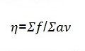
The rate of reaction is usually a function of the density of neutrons, their speed, and microscopic cross section of the medium for the reaction type x. It can be determined using the formula below:

The system controlling the reactor maintains chain reaction at a desired constant state. It achieves this by keeping track of the ratio between the number of neutrons of a single generation and that of the next are at a reasonable range. The ratio is also commonly referred to as the multiplication factor. It is denoted as k. It is calculated using the formula below:
k=Number of neutrons in current generation/ Number of neutrons in the preceding generation.
After leaving the fuel assemblies, the now hot water continues to flow upwards towards the outlet headed for the steam generators.
Reactor safety
PWR plants play an important role in the generation of electricity. However, they also pose potential harm to human existence. Radiations from the fuel used in the reactors can cause serious health problems, such as cancer and other genetic disorders. In order to minimise the exposure to the public, countries are urged to use nuclear power responsibly (Kim 2011). A number of principles have been adopted and incorporated to the designs of the PWR plants across the world. They serve as the guiding principle and help improve on reactor safety. The principle states that the public and the environment are put at minimum risk from the fuel used in the PWR reactors provided that the following guidelines are adhered to:
- The power of the reactor is controlled. To achieve this, the reactor should be closely monitored at all times (Kim 2011). The functioning of all the support systems, such as the pressuriser should also be monitored in order to ensure that all the parameters are maintained at norm.
- The fuel should also be cooled adequately. For this to happen, all the components of the PWR plant should be working efficiently. The reactor coolant system plays the greatest role in lowering the temperatures of the fuel. The reactor coolant pump should be functioning in the right manner in order to ensure that there is adequate circulation of the reactor fuel at all times.
- Radioactivity should also be contained. All the radioactive material should be safely stored within the facility. Leakages should also be avoided, especially within the reactor coolant system since this would result in unwanted exposure to radioactive elements. During maintenance and waste processing, the products generated should also be stored or disposed safely to reduce the risk of future exposure. Members of the public should also be discouraged from occupying the land adjacent to the PWR plants to lower their risk of being harmed by radiations emanating from it.
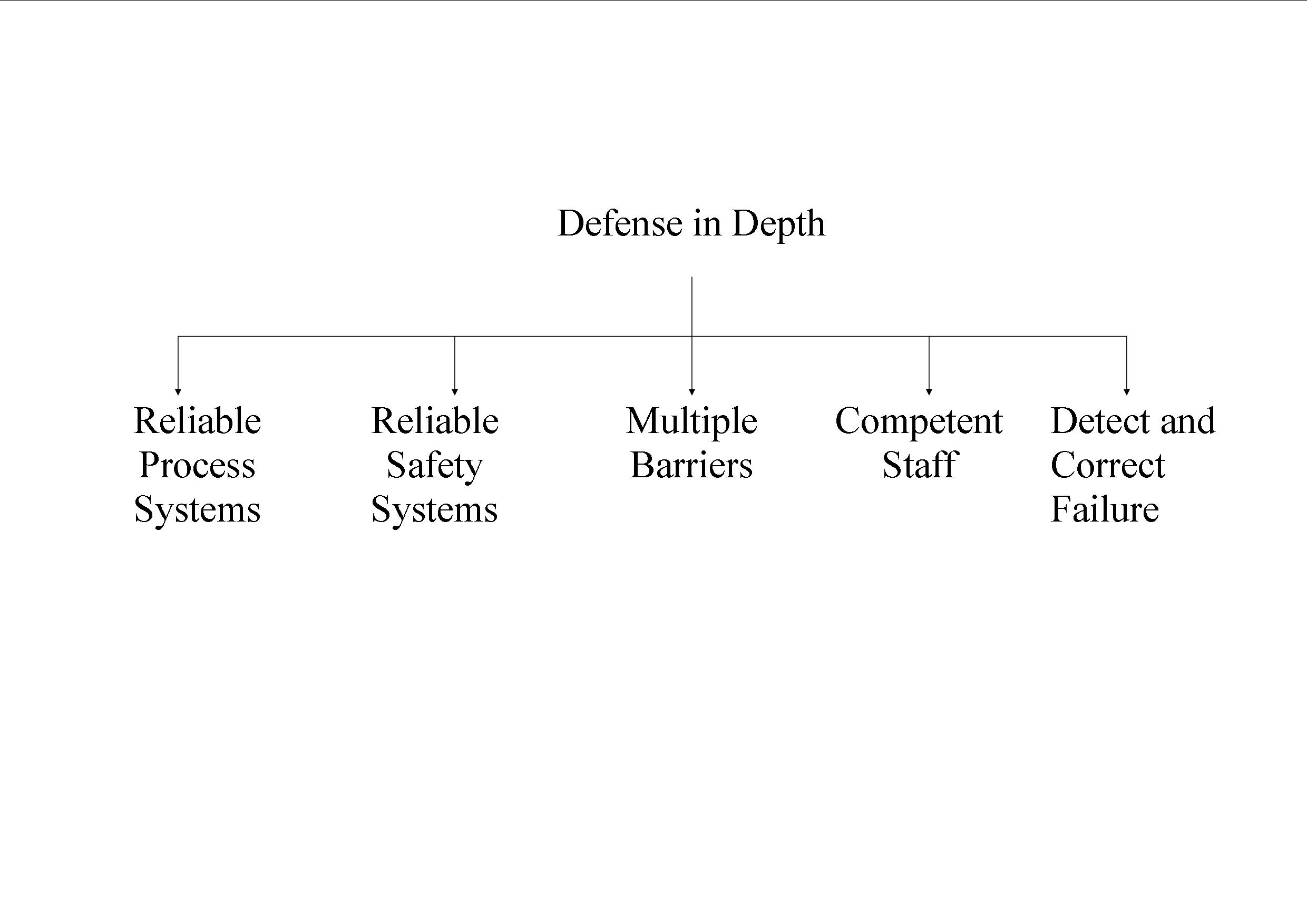
The guideline is often simplified as control, cool, and contain. There are many ways in which the three guiding principles can be achieved. Together, they have been used to come up with a concept referred to as ‘defence in depth’. They are adhered to in all aspects of PWR plants (Kim 2011). They guide the process of designing, constructing, commissioning, as well as operating PWR plants. The concept of defence in depth can be illustrated in a five model chart.
The chart below is an illustration of the five models of the defence-in-depth concept:
The concept operates under three major assumptions. They include:
- The design of the PWR plant will have some flaws. As such, problems should always be anticipated. Consequently, the personnel working in these plants must always be on the lookout. They must be able to anticipate these changes and deal with them effectively when they occur.
- Equipments used to construct the PWR plant will occasionally fail. In this case, constant monitoring will be required to determine the effect of the radioactive fuel on the strength of the material used to construct the reactor vessel (Kim & Lee 2011). As such, regular testing is needed. All employees should also be aware of the worst case scenario and know how to respond to it in the event that it occurs.
- Operating personnel are bound to make mistakes occasionally. As a result, the design should make it easy to reverse such actions without much damage. Warning systems should also be installed to detect malfunctioning caused by human error.
The key to ensuring defence-in-depth is ensuring that the flaws, failures, and mistakes that occur within a PWR plant is can be accommodated without raising the risk of an accident occurring (Li et al. 2006). The model shown above can be used to achieve this.
To begin with, the process systems should be reliable. They are the systems that perform a function on the plant continuously. Good examples include the primary reactor coolant system and the steam generators. In this case, the primary system will ensure that there is constant cooling of the reactor fuel. The steam generator too ensures that there is continuous transfer of heat from the primary to the secondary system (Nakath et al. 2013). In this case, reliability means that these systems will perform their intended functions as long as the plant is operational. As such, electricity generation will be on a continuous basis.
Reliable safety systems should also be put in place. They compensate for any failures that may occur within the process systems. A good example is the shutdown system. The personnel working in a PWR plant can be in a position to achieve this by deploying the emergency core cooling system (Bahn 2013). Reliability in this case means that in rare cases when the systems are required to intervene, they will be effective.
Multiple barriers, on the other hand, are aimed at preventing the release of radiations to the public. There are five barriers aimed at preventing the escape of radiations to the environment from the PWR plants (Bahn 2013). They include:
- The reactor fuel is moulded to ceramic pellets of very high melting points. As such, they lock in most of the products released following the fission process thus preventing them from entering the reactor coolant system.
- The fuel sheaths are made from zircaloy. It is a metal of high integrity. It houses the ceramic fuel.
- The primary reactor coolant system is made up of tubes that are of high strength. Its leak proof nature reduces the chances of spilling of the coolant.
- The system that is relatively leak proof is maintained below the atmospheric pressure. As such, it is a partial vacuum. It encourages air to leak into the system than out thus preventing the release of radioactive material.
- There is always an exclusion zone round the reactor. The zone has a radius of at least a kilometre. Radiations released from the PWR plant are diluted by the time the one kilometre barrier is crossed. As such, no harm will be caused to the public.
The technicians charged with the responsibility of operating and maintaining PWR plants should also be competent. It is noted that the plants are designed to operate automatically. However, the personnel present should not rely on the systems put in place to operate the plant. The reason is that occurrences of accidents cannot be ruled out completely when automation is used (Bahn 2013). They should be knowledgeable about the working of the system. They should also be in a position to anticipate risks and act promptly before accidents occur.
Failures in the system should also be detected and corrected promptly. Procedures and processes to be followed in times of system failure should also be always known to the personnel. In order to detect cases of failure, it is important to carry out routine testing (Li et al. 2006). The operations of the entire plant should also be put under surveillance to ensure that the systems and equipments repairs and replacement of components is done even before accidents arise.
Steam generators
After leaving the outlet nozzle of the reactor vessel, the coolant flows to the steam generators. It acts as the link between the primary and the secondary coolant systems. The number of steam generators present in a PWR plant depends on its kind, that is, whether it is two, three, or four-loop. Each steam generator is made up of many connecting tubes. The reactor coolant flows inside these tubes at high pressure and velocity (Madasamy et al. 2011). The secondary coolant, also commonly referred to as the feed water flows outside the tubes. In the process, it absorbs heat from the primary coolant. Up on absorbing sufficient amounts of heat, it boils to generate steam. Most variations are in terms of the mechanisms used to separate water and steam. The water content in the steam should be as low as possible. The aim is to avoid damaging the blades of the turbines.
There exist slight differences in the mechanism used to generate steam based on the design of the plant. The three most common are the Westinghouse, combustion engineering, and the Babcock & Wilcox designs (Madasamy et al. 2011). The functioning of the steam generators in the Westinghouse and the combustion engineering designs is basically the same. Up on heating, a mixture of water and steam is generated. The two are then taken through a series of moisture alienation phases. In the first stage, the mixture is spun. As a result, water is slung to the outside. The water is drained back to the first stage and is used to generate more steam (Lee et al. 2005). The steam collected in the first stage proceeds to the second. The second stage involves changing orientations. The mixture is made to shift direction rapidly. Water is heavier than steam. As such, it cannot change its direction as fast as the gas. It is collected and returned to the first stage. Steam on the other hand is light and is able to make the directional changes. It eventually escapes the steam generator. The system is said to be highly efficient. Every 100 pounds of steam that is generated contains less than 0.25 pounds of water.
On the other hand, the Babcock & Wilcox design is popular for applying a Once Through Steam Generator (OTSG). The primary coolant flows from the top to bottom of the steam generator down (Nakath et al. 2013). As the primary cooling agent flows, it gives out heat to the secondary system. The heat transfer is so great that the secondary coolant is heated above boiling point. As a result of superheating, the steam that is generated in this design is dry. As such, no separation is required to be carried out.
The manner in which the primary coolant and the steam leave the steam generator also depends on the type of PWR plant design. A case in point is the Westinghouse steam generator. It has only one outlet. The primary coolant also exits the generator via one outlet. On the other hand, the Combustion Engineering and the Babcock & Wilcox designs have two steam outlets (Krepper 2013). They also have a pair of primary coolant outlets. The steam generated is channelled into the central turbine. The primary coolant on the other hand is routed the primary coolant pump. The cycle is recurring throughout the period that the PWR plant is on.
The Secondary System
Once the secondary coolant leaves the steam generator, it is routed towards the main turbine. Unlike the reactor coolant, the contents of the secondary system contain little or no radioactive particles. The reason behind this is that the two are physically separated. The piping network within the secondary coolant system mainly carries steam (Krepper & Schaffrath 2013). As such, it is often referred to as the steam system. Once the steam enters the turbine compartment, it is of very high pressure. As such, it is directed to the central turbine. From there, it heads for the lower pressure turbines. However, since its pressure has considerably lowered after driving the main turbine, it has to be reenergised first. In order to achieve this, its water content has to be reduced once again in order to achieve dry steam. The moisture separator/re-heaters (MSRs) plays the role of drying the steam. The MSR have two major components. The two are the moisture separators and heaters.
Steam from the central turbine is circulated. It first enters the moisture separators. The dry steam generated in this compartment is then routed to the re-heaters. The water that is extracted is collected and returned to the steam generators. The dry steam on the other hand is reheated in order to increase its pressure. Heating is achieved by passing it hotter steam outside the piping. The now hot steam leaves the MSR and is routed to the low pressure turbines (Krepper & Schaffrath 2013). It is then taken to the main condenser. The main condenser is unique. It usually operates in vacuum. The condition provides a suction force. The suction helps boost the pressure of the steam as it passes through the low pressure turbine. As such, the system is efficient since the steam is relieved of most of its energy.
The turbine
The secondary cooling agent from the steam generator is taken directly to the pressurised central turbine. It enters through two steam chests located on opposite sides (Lips 2005). Each steam chest has a pair of throttle-stop valves. It also has another pair of governing valves. The governing valve is connected to the four inlet pipes each connected to nozzle chamber located inside the turbine cylinder. Two of the pipes are located on the base of the cylinder. The remaining two are in the cover. The flow of the steam is axial, in both directions originating from the nozzle chambers. It flows through the control stage into the reaction blading. From this point, it flows into the exhaust openings. They are six in number, three at each of the two ends. Two of the exhaust openings are located at the base of the cylinder and one in its cover. From this point, the steam collects in the cross-under piping and is routed to the MSRs before going to the low pressure turbines (Lee et al. 2005). The cross-under and the crossover piping system are fitted with a diaphragm link expansion joint which is hinge-type. The joint plays a role of absorbing the differential movement of the pipes.
The low pressure turbines also use double-flow. It achieves this with the help of a pair of steam chests. They use reaction blading to tap the energy contained in the steam. Steam is routed to the centre of the blades through the use of steam inlets located just below the horizontal joint and another at the side (Lee et al. 2005). After flowing through the blades, the steam is routed to an exhaust opening. The low pressure turbines have two exhaust openings. Each end has a single exhaust opening. The cylinders of the turbines have openings through which steam can be extracted before being taken to the condenser. The steam is used for providing additional heating to the secondary coolant system. The steam that exits from each of the exhaust openings is routed to the condenser. The energy transferred to the turbines from the steam is used in electricity production in the generators.
The generator
It is important to note that PWR plants are large nuclear stations with a main generator at 60Hertz. Its stator winding is cooled using water that has been demineralised. The water is normally supplied to the installation at a low pressure than that of hydrogen gas (Krepper & Schaffrath 2013). The stator core, its laminations, and its winding assembly are mounted on a spring that is flexible. The reason behind this is to avoid vibrations of double frequency that are generated inside the stator core. The rotor of the generator is cylindrical in shape. It is made of steel alloy. The combination is strong and permeable. It is produced through degassing inside a vacuum.
The generator is cooled on the inside using hydrogen gas. The gas is under high pressure compared to the water that cools the outer parts. It is normally at 60 psig. In other cases, the pressure of the gas may be as high as 75psig. Usually, the power factor of the generator used is 0.9 with a 0.58 short circuit ratio. The generator’s exciters are blushless and air cooled. They are shaft driven rectifier type. The speed of the generators used in PWR plants are 1800 rpm. Their rating is also high at 1370mva (Lee et al. 2005). The generators are also of the three-phase type. They produce 24000 to 26000 volts at 60Hz.
The generators are ventilated using hydrogen gas. The gas is usually circulated within the components of the generator with the help of a blower which is mounted on the rotor (Lee et al. 2005). The gas passes through the hydrogen coolers. Here, heat is normally passed on to service water. The now cold gas passes through the internal ducts that are located inside the frame. It then enters the holes that are located at the cores exciter end. It passes axially through the core before eventually being routed back to the blower. Part of the cold gas passes through the rotor through the aid of ventilations and baffles. It is important to note that gas enters each end of the rotor. It then flows through a space commonly referred to as the ventilating passage. Inside the rotor is a copper lining which facilitates direct cooling. It is usually discharged from holes that are located at the rotor’s centre and return through air gaps back to the blower. It is then circulated again. The cycle is continuous. Hydrogen gas is recycled hence making the system economical.
The condenser
It is also important. The steam first leaves the low pressure turbines. It is then taken to the central condenser that operates in a vacuum. The steam is cooled down to form water. The change is achieved with the help of cold water that circulates through tubes. The condensed steam, now water collects into the hot well, which is part of the main condenser system. From here, it is pumped by the condensate pump to the clean up system (Krepper 2013). The main role of the clean up system is to ensure that impurities present in the water are removed. The purification of water is vital since the steam generator plays the role of a concentrator. As such, the impurities will remain in the steam generator. The reason behind this is that steam is only composed of pure water. Accumulation of impurities in the steam generator will hinder the efficiency of heat transfer from the reactor coolant to the feed water system. It would also cause damage to the pipes of the steam generator.
The water from the condenser then leaves the clean up system. It then flows through heaters. The heaters are at low pressure. Steam extracted from the low pressure turbines is used for the purpose of heating at this stage. Through heating, the pressure of the feed-water system is further raised. The heating also increases the efficiency of the PWR plants since lesser energy will be required to generate steam to drive the turbines (Krepper 2013). The now pressurised water enters the steam generator. It is important to note that the rate at which water enters the steam generator is carefully monitored to avoid damaging the system.
Waste Processing and Treatment in PWR Plants
It is important to note that PWR plants produce waste in three main forms. They include, gas, solid, and liquid (Li et al. 2006). The waste product are produced both as the plant is running and also upon shutdown. The three forms are processed and treated using different systems. The system used to process liquid waste is mainly involved in its monitoring. It is also involved in its collection from the various components of the plant. Upon collection, processing commences. Most of the liquid waste is water. It is recycled for use in the plant. The system involved in the processing and treatment of gasses is mainly involved in its collection. The waste gas is stored for an unspecified amount of time which facilitates the decay of the radioactive fission products (Li et al. 2006). Eventually, the waste gas is released into the atmosphere. The solid waste system also plays an important role in pollution reduction. It is involved in the processing and treatment of the waste products that cannot be recycled. The volumes of these products are significantly reduced before being packaged safely for disposal.
It is also important for operators of PWR plants to seek ways to reduce the amount of waste generated. They could achieve this by using the available resources, such as water and reactor fuel economically yet maintain high production.
The graph below illustrates that it is possible to cut the amount of waste generated at a relatively rapid level:
Liquid Waste Processing and Treatment System
The system is used for handling and processing radioactive liquid waste generated within the plant. Most of the waste is from the primary system. The waste processing system receives the waste and segregates it (Bahn 2013). The various components of the waste are then processed into less harmful products. The system also plays an important role in the monitoring of the waste generated. It facilitates the recycling of all the affluent produced within the primary system for reuse. It is important to note that tritium is the radioactive waste contained in the primary system. Water containing tritium is separated from that which does not. With the separation, it is easier to control the concentration of tritium in the primary system.
The system is composed of a number of tanks. They are used for the purpose of collecting and holding liquid waste from the PWR plants. The system also has additional components, such as pipes, evaporators, pumps, monitors, demineralisers, and filters. The main source of the liquid waste in PWR plants is the primary system (Bahn 2013). However, it may also be generated from other areas, such as hot showers, laundry, laboratory, as well as equipment and floor drains (Lips 2005). The waste from all these areas is collected into their respective holdup tanks. Following the collection, processing commences. Waste that is meant for disposal is also processed to avoid pollution. Evaporators are the most commonly used means of waste disposal in the liquid waste processing system of a PWR plant. The use of reverse-osmosis waste packages is also common. After processing, analysis of the samples is done before a decision can be made on whether to dispose or recycle.
The design of the liquid waste processing system targets the minimisation of environmental pollution. The engineers involved in the construction of the system should also anticipate faults in the system that may result in the production of huge quantities of liquid waste (Li et al. 2006). Such cases occur in times of leakages in the system. With the system being capable of handling additional capacity, power generation in the PWR can be varied. The provision of additional capacity also increases the flexibility of the plant. It can be operational for a long duration of time before shutdown due to lack of capacity to accommodate additional waste.
Gaseous Waste Processing and Treatment System
The system receives gaseous waste. It deals with noble fission gas from the reactor coolant system. The gas is collected with the help of hydrogen which serves the purpose of a carrier (Lee et al. 2005). Once the fission gas has been removed from the primary system by hydrogen, its concentration is considerably lowered. One of the main advantages associated with this is that lesser quantities of radioactive gasses are released when the primary system is undergoing maintenance. The release of fission gasses through accidental leaks of the primary coolant will also be lowered. The system is normally made up of several key components. They include a charcoal absorption bed, surge tank, and recycle line compressors. It also consists of guard beds and a filter for the charcoal fines.
The hydrogen transmits the fission gas. It is initially contained in the volume control tank. It is then introduced to the gas drier containing refrigerated waste. The hydrogen gas is cooled. As a result, the hydrogen steam condenses removing water vapour (Lee et al. 2005). The now dried gas is routed to the guard bed. It is important to note that the guard bed serves the purpose of protecting the charcoal absorption bed from water. The entry of water may lead to contamination. The waste gas is then passed through charcoal absorption tanks. Here, the noble gasses produced following fission are absorbed. The gasses experience delay here before their release. Different gasses have different delay times. For example, Xenon-133 is taken through a 60 day delay before its release into the atmosphere. Krypton-85, on the other hand, is only delayed for four days. By the time of release, the radioactive gasses will have experienced decay. The amount of radiation emanating from such waste is, as a result, negligible
Unlike the noble fission gases, hydrogen is not delayed. It can pass through the charcoal bed (Kim 2011). The flow of the gas within the system is routed to the vent of the plant. Recycle line compressors also play an important role within the system (Kim 2011). They enable it to process gases that emanate from other parts of the PWR plant. They achieve this by routing the gases produced within all regions of the plant to the volume control tank where they undergo processing. In addition, the compressors are used for recycling hydrogen gas, which is reused in the primary coolant system. As such, PWR plants will operate more economically and efficiently.
Solid Waste Processing and Treatment System
The solid waste processing system is most concerned with volume reduction. It consists mainly of two systems. One of these is the radwaste volume reduction system. It is also commonly referred to as the radwaste solidification system. The other system is the radwaste incinerator. The two mainly deal with radioactive solid waste (Kim 2011). They reduce the volume of this waste before packaging it for safe disposal. It is important to note that only the plant waste of low level radiations is disposed. In some cases, the waste may be stored to prevent the release of radioactive material to the environment.
The reduction system plays a major role in maintaining the lowest volumes of solid waste. It employs cooled crystallisation. The process takes place in a vacuum. The process is also coupled with the mixing the waste with predetermined amounts of cement (Li et al. 2006). The process takes place at high speeds to ensure that all the waste particles are firmly bound. The role of cement in the process is to bind the particles together hence achieving solidification. By compacting the waste particles, lesser volumes will be produced which eases disposal and storage. Plant wastes that are combustible are incinerated. The process takes place using controlled air. Combustion helps burn out the solid waste to produce ash which is of lower mass and volume. Examples of waste products from the PWR which are combusted include clothing, wood, cartridges, and filters.
Besides radioactive materials, the volume reduction system also deals with other kinds of waste that cannot be recycled. It consists of four major systems. They include the condenser, the vacuum pump, crystallisation chamber, as well as the recirculation system (Li et al. 2006). Most of this waste includes the bottom contents of the evaporator tanks. It includes wastes emanating from boric acid, floor drains, as well as chemical waste. The crystalliser chamber of the system is a conical tank. Inside the tank is a circular baffle which serves the purpose of separating the solid crystals from the clear stream of recycled material.
The cement solidification system’s main aim is to compact. The technique is used to further process the waste whose volume has already been reduced. It may also be used for waste with low levels of radiation (Jung & Yeon 2010). Other waste products that are processed in the system include tools that are contaminated and resins. In order for the system to function efficiently, it has a number of components. They include the high shear mixer. It plays a role of mixing the waste particles together with cement to make a homogenous mixture. It also has a waste dispenser whose role is to eradicate the already processed waste from the system. The flush water recycle steam is another component. It provides heating. Other minor components of the system include the container handling system, cement storage, as well as the feed system.
Conclusion
The paper has described the operations of a PWR plant in depth. From the literature provided, it is evident that there are a number of advantages and disadvantages associated with the use of PWR plants as a source of electricity. One of the main advantages of the PWR plants is that the reactors are very stable since they tend to produce lesser amounts of electrical power as temperatures increase (Nakath et al. 2013). As a result, it is possible for the personnel working in the plants to operate without risks of accidents occurring. Another major advantage of PWR plants is that the primary and the secondary system are physically separated. As a result, contamination of the secondary system is negligible. In this case, only the coolant from the primary system needs to undergo intense treatment and processing. The PWR plants are also advantageous in that they have the ability to shut down the reactor in the event that there is a power outage. The reason behind this is that the electrical components of the plant use external sources of power in order to carry out their activities. In case of power outage, the fission process stops automatically (Lips 2005). The design of the PWR plants is also easy to manipulate. As such, it can be used to power different types of installations. Today, the system is being used to power submarines and naval ships.
However, there also exist a number of disadvantages associated with the use of PWR plants. To begin with, the water in the reactor coolant system must be maintained at high pressure and temperatures. The material required to construct the piping network should be of high strength. As a result, the cost of constructing the plants is very high. A lot of additional components such as the pressuriser, and the reactor coolant pumps. The need for these components further increases the amount of capital required. Steel is one of the most commonly available metals of high strength. In an ideal situation, it would be the most suitable for constructing components of a PWR plant. However, if the steel is not stainless, it may be corroded by boric acid present in the reactor coolant system. The resultant radioactive corrosion would significantly reduce the life of the reactor. The system that filters out corrosive materials could also be destroyed resulting to higher costs of operation (Lips 2005). The Advantages of PWR plants outweigh its disadvantages. As a result, the technology is quickly being adopted in many nations across the world.
References
Bahn, C 2013, ‘Chemical effects on PWR sump strainer blockage after a loss-of-coolant accident: review on U.S. research efforts’, Nuclear Engineering and Technology, vol. 12 no. 25, pp. 295-310.
Choi, K, Park, Y & Song, K 2013, ‘Determination of Thei in primary coolant of PWR’, Nuclear Engineering and Technology, vol. 3 no. 1, pp. 61-66.
Hohne, T & Kliem, S 2007, ‘Modelling of a buoyancy-driven flow experiment in pressurised water reactors using CFD-methods’, Nuclear Engineering and Technology, vol. 12 no. 31, pp. 327-336.
Jung, Y & Yeon, J 2010, ‘Fabrication and evaluation of a new high-temperature pH sensor for use in PWR nuclear power plants’, Bulletin of the Korean Chemical Society, vol. 3 no. 4, pp. 2939-2942.
Kim, I & Lee, U 2011, ‘Sensitivity analysis of depletion parameters for heat load evaluation of PWR spent fuel storage pool’, Journal of the Korean Radioactive Waste Society, vol. 12 no. 30, pp. 237-245.
Kim, J 2011, ‘Investigation on the preventative maintenance schemes for the dissimilar metal welds of components in nuclear reactor coolant system’, Journal of the Korean Welding and Joining Society, vol. 5 no. 4, pp. 13-20.
Krepper, E & Schaffrath, A 2013, ‘Actual status of the research alliances “condensation induced water hammer” and “boiling processes in pressurised water reactors”’, Kerntechnik, vol. 10 no. 19, p. 8.
Krepper, E 2013, ‘Modelling, simulation, and experiments on boiling processes in pressurised water reactors’, Kerntechnik, vol. 12 no. 19, pp. 35-37.
Lee, I, Yoo, C & Kim, K 2005, ‘Fault diagnosis for the nuclear PWR steam generator using neural network’, Journal of Fuzzy Logic and Intelligent Systems, vol. 12 no. 4, pp. 673-681.
Lee, J, Kim, D, Bang, K, Seo, K, Choi, B & Lee, H. 2005. ‘Thermal analysis of a storage cask for 24 spent PWR fuel assemblies’, Packaging, Transport, Storage, and Security of Radioactive Material, vol. 2 no. 1, pp. 19-26.
Li, J, Ye, Y, Shi, Z & Wang, J. 2006. ‘Calculation and usage of containment monitor radiation readings during PWR accidents’, Journal of Hazardous Materials, vol. 3 no. 1, pp. 177-181.
Lips, M 2005, ‘Water chemistry in pressurised water reactors: a Gösgen-specific overview’, CHIMIA International Journal for Chemistry, vol. 12 no. 12, pp. 929-937.
Madasamy, P, Subramanian, H, Mohan, T, Velmurugan, S, Natarajan, E & Narasimhan, S. 2011. ‘Experimental determination of flow accelerated corrosion in bend and straight sections of carbon steel primary coolant feeder pipes in pressurised heavy water reactor system’, Corrosion Engineering, Science, and Technology, vol. 12 no. 1, pp. 346-352.
Nakath, R, Schuster, C & Hurtado, A 2013, ‘About the change in boiling behaviour of water with coolant additives in PWR’, Kerntechnik, vol. 3 no. 1, pp. 72-73.