Introduction
A simulation uses a model to analyze the behavior and performance of a natural or theoretical system. In a simulation, models may be used to examine current or projected system properties (Chen and Liu, 2018). The Finite Element Analysis (FEA) is the modeling of any given physical phenomenon using the numerical approach called the Finite Element Method (FEM) (Samadi et al., 2022; Shih, 2018). Engineers utilize FEA software to minimize the number of physical prototypes and trials and optimize components in their design process to build better products quicker while saving on expenditures (Singh, Ahmad, and Saini, 2019; Reddy and Nagaraju, 2019). Mathematics is required to comprehend and quantify any physical phenomenon, such as structural or fluid behavior, heat transfer, wave propagation, or the proliferation of biological cells (Loney, 2019). An example is a bridge bearing pad or the warren truss bridge, which is analyzed in this study.
Objectives
The FEA simulation is guided by the following objectives:
- To solve a bridge truss as shown on the blackboard.
- To perform a linear statistic structural analysis in ANSYS.
FEA Simulation Procedure and Setup details
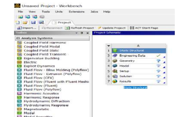
Step 1: Modeling of truss with ANSYS Program Selected “Static Structural” and placed on the homepage of ANSYS workbench application.
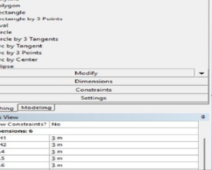
Step 2: Drawn the truss use with “Designmodeler” option in “Geometry” and entered dimensions like was given.
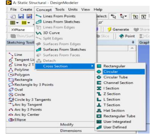
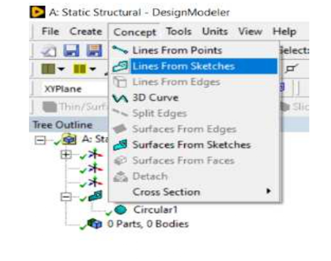
Step 3: Selected “Concept” to “Cross Section” and applied “Circular” for the model.
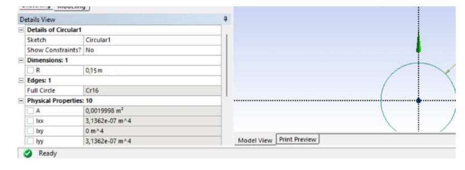
Step 4: Entered 0.15m for cross-section radius to all elements.
Step 5: Selected “Lines from Sketches” from “Concept” menu to create a combined truss structure.
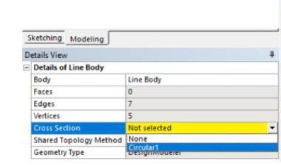
Step 6: From “Details of Line Body” selected “Circular1” for “Cross Section”.
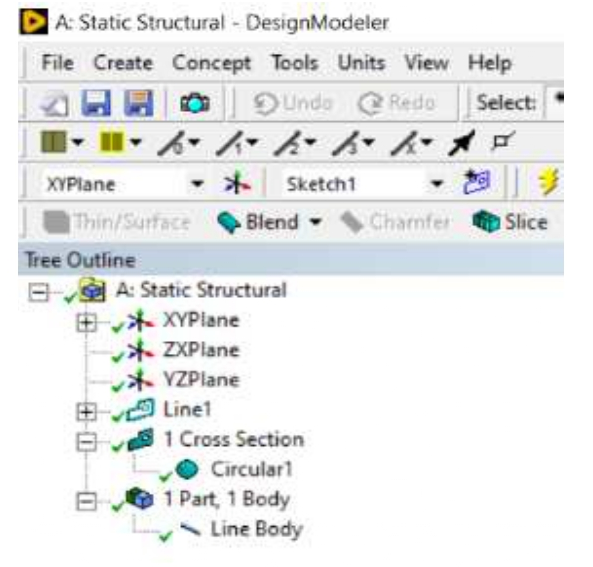
Step 7: Generated cross-section command and completed modeling.
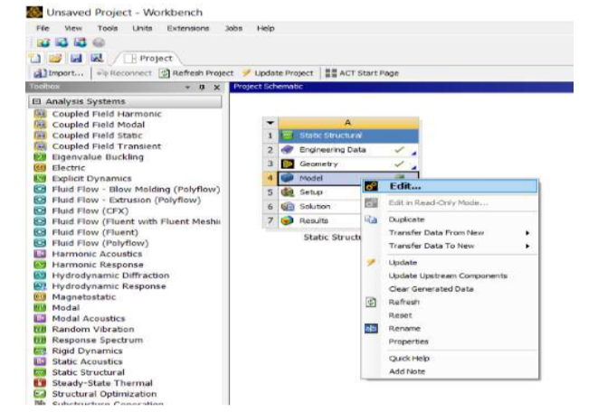
Step 8: Selected “Edit” command from “Model” button in workbench to enter conditions like supports, and forces.
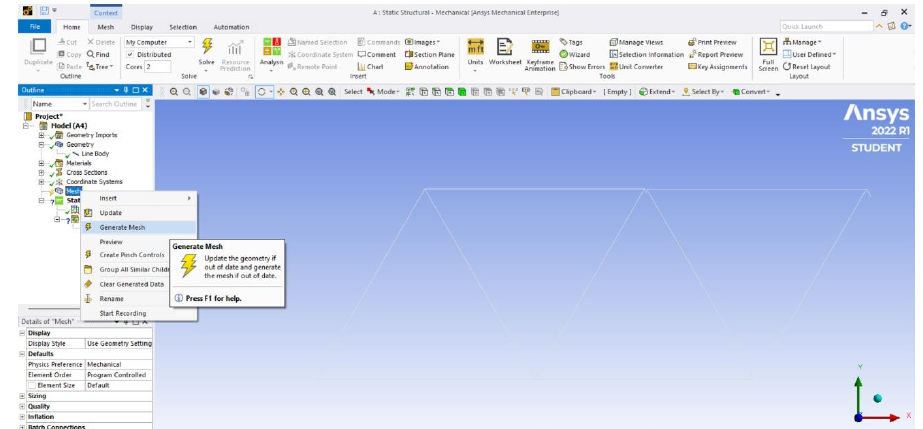
Step 9: Generated mesh for slicing elements.
Step 10: Selected “Fixed Support” from “Insert” from “Static Structural” options.
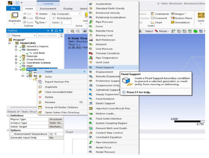
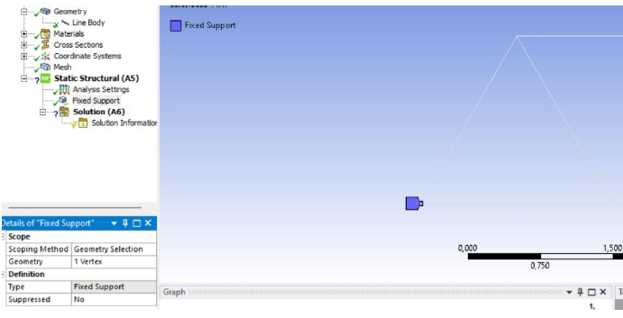
Step 11: Added “Fixed Support” to left starting point.
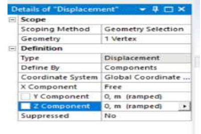
Step 12: Selected “Displacement” from “Insert” from “Static Structural”
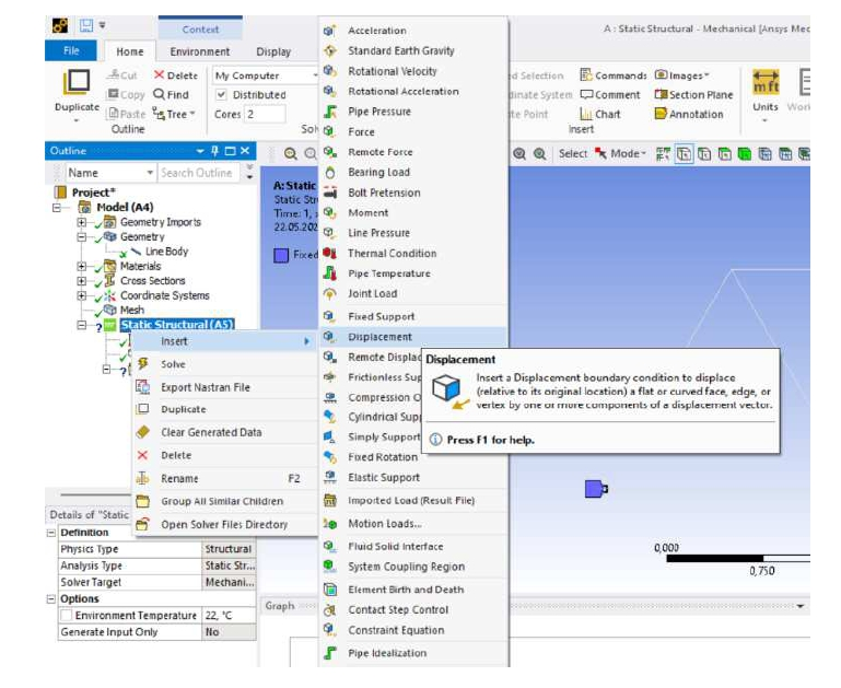
Step 13: Added “Fixed Support” to left starting point and entered 0 m for A, E components.
Step 14: Added “Force” from “Insert” option
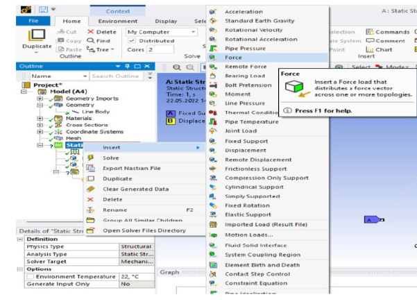
Step 15: Entered 6kN to -Y direction like shown in figure
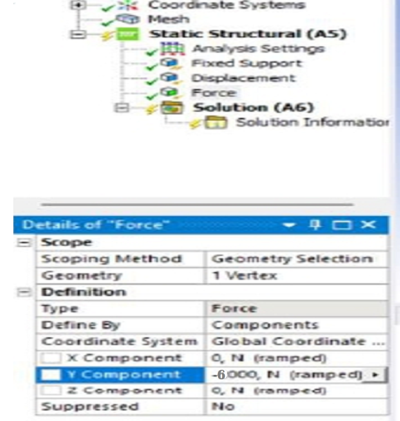
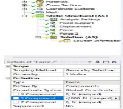
Step 16: Added “Force” to analysis. The second force is 8kN to -Y direction.
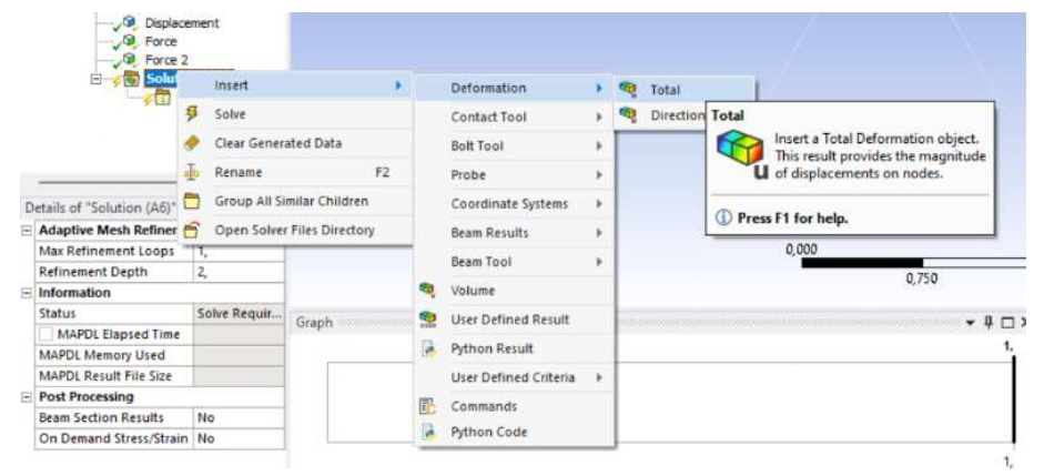
Step 17: Added total deformation to solution for see deformations on the results.
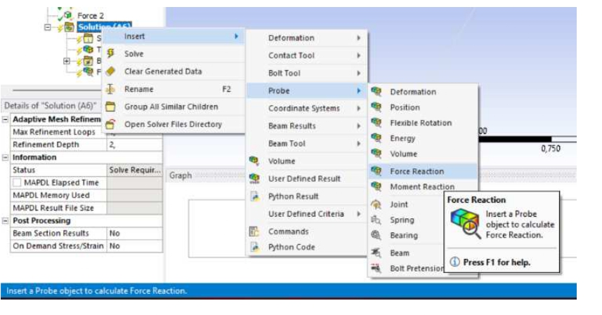
Step 18: Added “Force Reaction” to solutions for see reaction forces on the results.
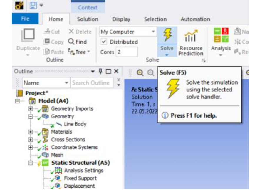
Step 19: “Solve” command executed and program calculated results.
Results and Analysis of those Results
Results of Showed total deformation and location
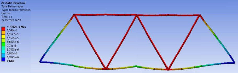
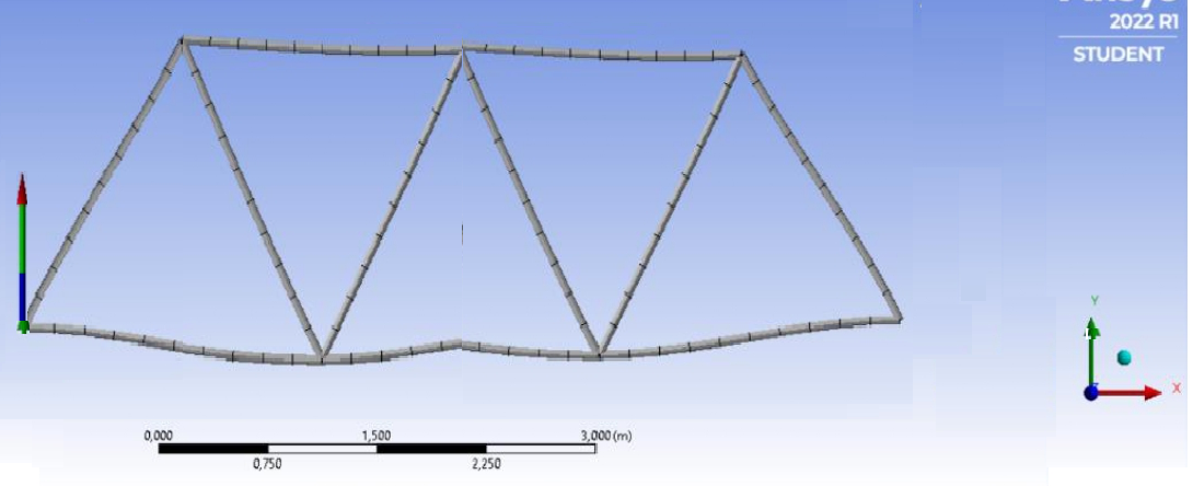
Table 1: Tabular data for reaction forces for Node A

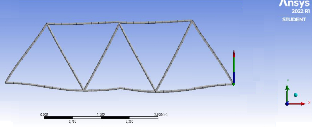
Table 2: Tabular data reaction forces for Node E

Location of the Frame Undergoing Maximum Deflection
Table 3: Node A (Fixed Support)

Table 4: Node E

Manual Calculations
The moment of a force is defined as the product of the distance from a point to the point of application of force and the element of the force that is perpendicular to the line of distance.
M = F·d
Momentum (M) measures a force’s turning impact or rotational capacity. Moments of all applied forces must equal zero for a structure to be in equilibrium (Mahdavi, 2020; Praisach and Pirşan, 2022). In this blackboard example, forces F1, F2, and F3 tend to spin the truss clockwise concerning node 1, but the response force R7 on node 7 cancels this effect, maintaining the truss’s equilibrium (Lindstrom, 2019; Emri and Voloshin, 2018). This equilibrium condition is theoretically defined as the total of all forces and reactions equal to zero moments.
M1 = ƩF1· x1 = 0 (9)
= R1 · 0 – F2 · 1.5 – F3 · 3- F4 · 4.5 + F5. 6+F6 .7.5+R7 · 9 = 0
For this example, given F1 = F2 = F3 = 6kN, the value of reaction R7 can be found solving equation (9):
= R1 · 0 – 6kN · 1.5 – 6kN · 3 – 6kN · 4.5 + 8kN · 6+8kN · 7.5+ R7 · 9 = 0
-60 + R7 · 9 = 0
R7 = 6kN
And the value of reaction R1 can be found solving equation (9):
= R1 · 9 – 6kN · 4.5 – 6kN · 3 + 6kN · 1.5 + R7 · 9 = 0
R1 · 9 – 54 = 0
R1 = 6kN
Analysis of Forces on Nodes using FBD and the equilibrium conditions ƩFy = 0 and ƩFx = 0.
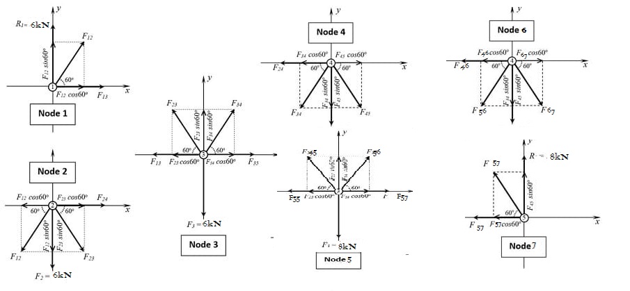
Node 1
∑Fy=0. Analysis of forces acting along the y-axis.
R1+F12sin600=0
Or 6kN+0.866F12=0………………………………………………… (0)
∑Fy=0. Analysis of forces acting along the x-axis:
F13+F12cos600=0
Or F13+0.5F12=0……………………………………………………. (1)
Node 2
∑Fy=0. Analysis of forces acting along the y-axis.
-F2-F12sin600-F23sin600=0
OR -6Kn-0.866F12-0.866F23=0…………………………………………. (2)
∑Fy=0. Analysis of forces acting along the X-axis
F24-F12cos60+F23cos600=0
Or F24-0.5F12+0.5F23=0………………………………………………… (3)
Node 3
∑Fy=0. Analysis of forces acting along the y-axis
-F3+F34sin600+F23sin600=0
or -6kN+0.866F34+0.866F23=0…………………………………………. (4)
∑Fy=0. Analysis of forces acting along the x-axis
-F3-F23cos600+F34cos600+F35=0
Or –6kN-0.5F23+0.5F34+F35=0……………………………………..…. (5)
Node 4
∑Fy=0. Analysis of forces acting along the y-axis
-F4+F34sin600-F45sin600=0
Or -6kN-0.866F34-0.866F45=0……………………………………..…. (6)
∑Fy=0. Analysis of forces acting along the x-axis:
-F4-F34cos600+F45cos600=0
Or –F24-0.5F34+0.5F45=0…………………………………..…………. (7)
Node 5
∑Fy=0. Analysis of forces acting along the y-axis
-F5+F56sin600+F45sin600=0
or -8kN+0.866F56+0.866F45=0…………………………………………. (8)
∑Fy=0. Analysis of forces acting along the x-axis
-F5-F45cos600+F56cos600+F57=0
Or –8kN-0.5F45+0.5F56+F57=0………………………………….……. (9)
Node 6
∑Fy=0. Analysis of forces acting along the y-axis
-F6-F56sin600-F67sin600=0
Or -8kN-0.866F56-0.866F67=0……………………………….……….. (10)
∑Fy=0. Analysis of forces acting along the x-axis:
-F46-F56cos600+F67cos600=0
Or –F46-0.5F56+0.5F67=0…………………………………..….….….. (11)
Node 7
∑Fy=0. Analysis of forces acting along the y-axis
R7+F67sin600=0
Or 8kN+ 0.866F67=0…………………………………………………… (12)
∑Fy=0. Analysis of forces acting along the x-axis
-F57-F67cos600=0
Or –F57-0.5F67=0………………………………………………..…… (13)
The solution of this system will give the values of the tension-compression forces on the truss elements because the 6Kn and 8KN loads (Potter and Nash, 2019). The forces are as shown below:
- Compression Force
6kN+0.8666F12=0
F12=-6kN/0.8666= -6.923 kN (Compression)
- Tension Force
F13+0.5F12= 0
F13+0.5(-6.923) = 0
F13 = 3.3615 kN (Tension)
- Shear Force
-6kN-0.866F12-0.866F23=0
-6kN- 0.866(-6.923) – 0.866F23=0
F23 = 0 kN. (Shear Force)
Conclusion
From the above calculations, the results of the reaction forces and nodal displacements discovered using ANSYS and through manual solution were slightly different. Therefore, issues requiring the finite element method may be successfully handled using the ANSYS application. Different design engineers utilize different ways to assess trusses. Using the FEM, one can often only anticipate an approximation of a solution. This is because the precise solution for the truss deformation is a first-degree polynomial. This form of load might be introduced in the future development of this program. Additionally, it would be advantageous to broaden analysis so that not only planar but also spatial issues may be solved.
Reference List
Chen, X. and Liu, Y. (2018) Finite element modeling and simulation with ANSYS Workbench. Florida, FL: CRC press.
Emri, I. and Voloshin, A. (2018) Statics: Learning from engineering examples. New York, NY: Springer
Lindström, S. (2019) Lectures on engineering mechanics: statics and dynamics. New York, NY: Amazon.
Loney, S.L. (2019) The elements of statistics & dynamics part-i statics. New Delhi: Arihant Publications.
Mahdavi, M. (2020) ‘Evaluation and comparison of seismic performance of structural trusses under cyclic loading with Finite Element Method’, International Journal of Civil and Environmental Engineering, 14(10), pp. 341-348.
Potter, M. C. and Nash. W. (2019) Schaum’s outline of strength of materials. 7th edn. New York, NY: McGraw-Hill.
Praisach, Z.I. and Pîrșan, D.A. (2022) ‘The influence of the truss bar on the dynamic behavior of a Warren truss by changing the modulus of elasticity’, Vibroengineering PROCEDIA, 46(1), pp. 41-47.
Reddy, P.S.K. and Nagaraju, C. (2019) ‘Structural optimization of different truss members using finite element analysis for minimum weight’, International Journal of Mechanical and Production Engineering Research and Development (IJMPERD), 9(4), pp. 99-110.
Samadi, S. et al. (2022) ‘Thermomechanical finite element modeling of steel ladle containing alumina spinel refractory lining’, Finite Elements in Analysis and Design, 206(1), p.103762.
Shih, R. (2018) Introduction to Finite Element Analysis using solidworks. Oregon: SDC Publications.
Singh, A., Ahmad, F. and Saini, N.K. (2019) ‘Finite Element Analysis based vibration behavior on Warren Truss Bridge’, International Journal of Applied Engineering Research, 14(9), pp. 215-219.