Background
Fiber Optic Transceiver is a component that transmits and receives information through its self-contained components. The component is inserted into others devices as a network interface cards or routers. Such devices usually one or multiple transceiver module slots usually labelled as SFP, GBIC, and XFP just to mention a few. There are several optical transceivers, which perform different tasks. These transceivers include SFP+ (SFP Plus) transceiver, XENPAK transceiver, XFP transceiver, X2 transceiver, SFP (Mini GBIC) transceiver, CWDM/DWDM transceiver, GBIC transceiver, 40G QSFP+ and CFP, PON transceiver, 3G-SDI video SFP and WDM Bi-Directional transceiver (Brillant 112). The aforementioned transceivers operate in significant ways and should be compatible with the main brands such as HP, Juniper, Nortel, Cisco, Force 10, D-link and 3Com (Reviriego et al. 3). The transceivers can undergo customization to suit the specifications of the intended requirements or applications. This research focuses on the CFP transceivers.
How CFP Optic Fiber Transceiver works
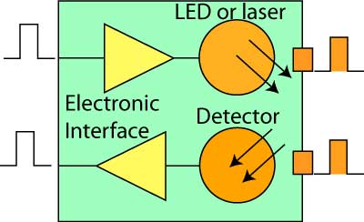
Brillant (89) outlines that the information sent from the pulses of light enters the fiber optics, which converts the light to electrical components that allows their utilization by the electronic device. The converted optic signal is thereafter undergoes a transmission through fiber optic cable. The cable’s terminal experiences some lighting, which a detector changes to electrical signal. The indication of the presence of light source is possible using a light emitting diode (LED) or a laser diode. The transmission and reception of signals uses a two-way system. The transmission and reception work synergistically in a full duplex operation model. The transmission follows a unidirectional path as the reverse path to transmission the optical fiber receives the signals.
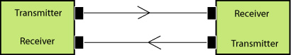
The optic transceivers of most systems constitute both a transmitter and a receiver within a single module. The transmitter changes electrical input that comes from a light emitting diode to optical output. The receiving equipment requires proper conditioning to ensure efficiency in reception of the optic signals.
The transmission sources of fiber optic affect the reception of such signals. Therefore, for effective receiving of the signals, the transmission must ensure a certain specified criteria. Only light of a given wavelength is receivable by the optical transceivers. The light source needs a fast modulation to reach the fiber cables. Four systems commonly used in modulation include fabry-perot (FP) lasers, distributed feedback (DFB) lasers, LEDs and vertical cavity surface emitting lasers (VCSELs). Reviriego et al. (7) record that these components also convert electrical signals to optical signals. The components consist of chips, with VCSELs and LEDs having fabrications on their semiconductor wafers to enable emitting of light from the chip’s surface. The FP lasers provide an emission from the side of the chip to the middle of the chip to enable proper conversion by the transceiver.
The choice of the transmission devices defines the kind of transceiver used. Specifications such as speed and fiber compatibility are important in choosing the transceiver. Systems that use multimode fiber have higher bit rates of 1 Gb/s (Cisco 2). Such range is only possible in VCSELs. Such lasers provide more focused optical outputs with defined modal fill. Secondly, the VCSELs are capable of making effective higher fiber bandwidth enabling the use of a wide range of transceivers. Therefore, most modern systems use VCSELs rather than the LEDs.
Types of CFP Fiber Optic Transceiver
The system of Form-Factor Pluggables (CFPs) transceiver operates on a Brocade 100 Gbps. This is a highly rated device with low voltage of 3.3V and hot-swappable digital diagnostic Ethernet. The system supports serial of high speeds approximated to be 2×12 multi-mode fibers. The efficiency of the Transceiver is its high signaling power, which estimates to 10×10.3125 Gbps (Reviriego et al. 8). Besides, the transceivers are compatible with the CFP MSA and optical IEEE 802.3ba specifications. One of the most common models of CFP transceivers is the Brocade 100 Gbps SR10 Ethernet optical transceiver, which constitutes a 10-lane with 10Gbps CFP enabling it to comply with the 100GBASE-SR10 requirements. The device operates within an optical interface provisions of IEEE 802.3ba 100GBASE-SR10. The device has other specifications such as control temperature, supply voltage, standard MPO24 connector with an estimated link length of 100m. Besides, the OM3 multi-mode fiber, which is 150m link length, provides a connection pathway to the OM4 multimode fiber. The transceiver also has an IEC 60825-1 Class 1/CDRH Class 1 laser eye safe, which regulates the entry of hazardous substances in the process of use.
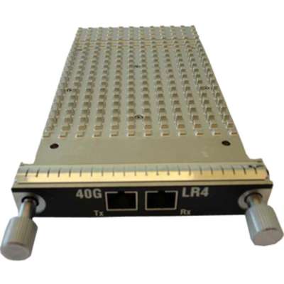
Notably, there are some CFPs with advance technology, which uses the 40GBASE CFP module. Such CFPs are capable of supporting long link lengths estimated to 10km. in such circumstances, the module applies the G.652 single-mode fiber by using the duplex SC connectors. Besides, the model uses multiplexing and de-multiplexing using the 40 Gigabit Ethernet signal to provide coverage to over four wavelengths (Sunaga et al. 177). The device has components that maintain the four wavelengths within the required range to enable proper functioning of the transceivers. Observably, in this case the CFPs can use either the IEEE 40GBASE-LR4 or the OTU3 C4SI-2D1 standards to create a focused optical signal. There still exist other more advance and technological devices capable of providing coverage of up to 2km. For instance, 40GBASE-FR CFP is capable of supporting links to an estimated length of 2km using the standard paired fiber with single-mode duplex SC connectors (Sunaga et al. 180). The CFP device uses a serial optical lane, which is at 40 Gigabit. This kind of CFP module uses both OTU3 VSR2000-3R2 and IEEE 40GBASE-FR standards.
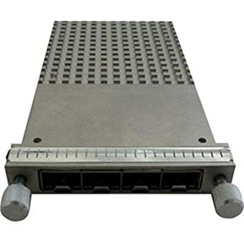
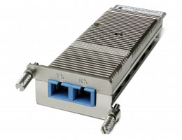
The conversion ability of FourX converter module shown in the picture below is important in providing the required structure that allows connection to multiple devices depending on the requirements of the user. It alters 40 Gigabit Ethernet CFP port into four autonomous 10 Gigabit Ethernet ports. Nevertheless, the system of the transceivers does not include the 10 Gigabit Ethernet SFP+ (Reviriego et al. 7).
Connectors and Cabling
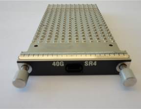
The models of the CFP use the 12-fiber female MTP/MPO connector for the SR4. The other models, LR4 and FR4, use dual PC/SC connectors. Such connectors have patch cords supported by the PC or UPC connectors (Green 3125). Notably, the system does not support other patch cords, which have connectors with APC. In each of the cases, the cables used must be compatible with the standard specifications for each of the defined modules applied. Each CFP module has specific specifications, which include wavelengths, core size, cable type modal bandwidth, and cable distance as outlined in the table below.
Table 1: cabling specifications for CFP Optic Transceivers (Sunaga et al. 179)
The information from the table shows a range of distance for each CFP cabling. The minimum cabling is observable in SR4 at 0.5m while the LR4 CFP having a longer length of up to 2m. Such cables also operate within a specified link. Engineered links provide up to 1dBconnections to reduce splice loss. Green (3126) asserts that the IEEE 802.3ba provides the specifications for the wavelengths and distances. The CFPs constitute major characteristics that define their applications and the various connectors required. The table below shows such characteristics.
Table 2: The main optical characteristics for CFP (Brillant 127)
The operations of the CFP transceiver also requires maximum outer dimensions of 144.8 x 82 x 13.6mm (Length x width x height). Besides, the CFP modules have a typical weight of 300 grams or less. Most CFPs have an operational temperature range of 0 to 700C (Cisco 3).
The Installation Procedure of the CFP
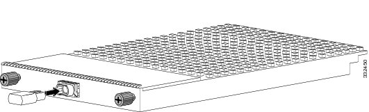
The connection procedure of the CFP transceiver applies almost a similar model. The systems connect to the electrical circuitry using the optical platform of the CFP. In order to achieve the best connection usage of the system particular instructions apply. The devices that use the transceivers have ports that are labelled for each of the transceivers. For instance, the 100-Gigabit and the 40-Gigabit transceivers have hot-swappable I/O sections that plug into the various ports of the other device. The first stage in the installation process involves connection to the ports. An example is as shown in the connection for CFP-40G-LR4 using the duplex fiber connectors (Wipiejewski et al. 114). The other CFP components, the CFP-40G-FR and CFP-100G-LR4 can also apply the SC fiber connectors.
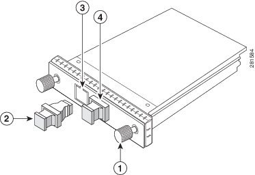
The 12-fiber MPO adapter used in CFP-40G-SR4 also depicts a comparable linking as that of the SC fiber adapters displayed earlier. Nevertheless, minimal changes in design are observable. The connection features are as shown in the diagram below. Another similar connector, the 24-fiber MPO connector, also uses the same connection for CFP-100G-SR10 (Wipiejewski et al. 117).
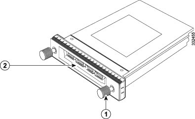
In some cases, the connection also uses a converter than provides a multiple connection possibilities. The system mostly applies to the CVR-CFP-4SFP10G module, transceiver that enables a wide range of application (Heikkinen et al. 1213). Figure 7 below shows the right installation model upon the use of a converter. The number 1 in the diagram represents captive installation screws whereas number 2 represents 10G SFP+ ports (4X).
Both the MPO and the MPO connectors use the network interface cables together with either Ultra-Physical Contact (UPC) or Physical Contact (PC). Nevertheless, since the two connectors are optical CFP transceivers, they are unable to work with the network interface cables using an Angle Polished Connector (APC) (Cisco 4). Importantly, an understanding of the various polished face types is necessary during the installation process.
Detectors of CFP Fiber Optic Transceivers
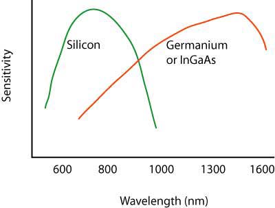
The CFP transceivers uses semiconductor detectors usually photodetectors and photodiodes. These diodes are capable of detecting and converting optical signals to electrical signals. Short wavelength optical signals are converted to electrical signals using silicon photodiodes. Short wavelength signals ranges from 650nm for POF fiber and 850nm for MM fiber (DeCusatis 129). On the other hand, the detection and conversion of long wavelength signals uses indium gallium arsenide (InGaAs) detectors. The efficiency of the InGaAs detectors is their ability to produce minimal noise enabling more sensitiveness during the process of detection and conversion. In other situations, a very high speed might be essential. Such systems with high-speed signal requirements use avalanche photodiodes (APDs). In the event, high-speed detection and conversion is possible (Green 3126). Even though the APDs produce significantly higher performance, the APDs are expensive and complex to use limiting their application. The graph below represents the sensitivity of each of the detectors within various wavelengths.
Notably, understanding the packaging design of CFP transceivers is important. The standard packaging systems consider the gigabit datalinks. During the packaging process, the CFP module and the duplex connector are placed together at the optical end with a standard electrical interface on the opposite end of the CFP. According to Heikkinen et al. (1215), the 10-Gigabit networks employ a SC duplex connection during packaging. The packaging of the converters uses a different set of structure from the CFP.
Performance of the CFP
According to DeCusatis (221), the determination of the performance of the CFP transceiver depends on the reconversion of the optical signal input into the electrical signal output. The transmitter defines the conversion strength of the optic fiber transceiver. The performance of the datalinks is also important in defining the general performance of the transceiver. The conversion process depends on the datalinks. Besides, the sensitivity degree of the transceiver together with the minimum power of the CFP fiber is important (Heikkinen et al. 1220). Additionally, the operating range depends on the signal-to-noise ratio (S/N). The performance of the CFP transceiver requires a higher S/N ratio to produce the required conversion standards.
Conclusion
An understanding of the basic principles of the CFP transceivers is important. The transceivers vary in density, speed and the networking applications employed. The choice of a specific transceiver requires prior knowledge of Ethernet, Bandwidth, Optical Transport Network (OTN), and Fiber Channel. This enables an extensive portfolio in determining the best connection, which meets the user’s requirements. The introduction of laser and IC technologies continue to develop the CFP transceivers.
References
Brillant, Avigdor. Digital and Analog Fiber Optic Communications for CATV and Fttx Applications. Bellingham, Wash.: SPIE, 2008. Print.
Cisco. Cisco 40GBASE CFP Modules. 2012. Web.
DeCusatis, Casimer. Handbook of Fiber Optic Data Communication. San Diego, CA: Academic Press, 2002. Print.
Green, Samuel. “Multichannel Bit Error Rate Tester for Fiber Optic Transceiver Testing.” Revolution Science Instrument 73.8 (2002): 3125-3127. Print.
Heikkinen, Veli, Teemu Alajoki, Eveliina Juntunen, Mikko Karppinen, Kari Kautio, Jukka-Tapani Mäkinen, Jyrki Ollila, Antti Tanskanen, Jaakko Toivonen, Rory Casey, Shane Scott, Wilhelm Pintzka, Sylvain Thériault, and Iain McKenzie. “Fiber-Optic Transceiver Module for High-Speed Intrasatellite Networks.” Journal of Lightwave Technology 25.5 (2007): 1213-1223. Print.
Reviriego, Pedro, Ben Huiszoon, Vincenzo López, Robert Coenen, Jose Hernández, and Juan Antonio Maestro. “Improving Energy Efficiency in IEEE 802.3ba High-Rate Ethernet Optical Links.” IEEE Journal of Selected Topics in Quantum Electronics 13.6 (2011): 1-9. Print.
Sunaga, Yoshinori, Ryuta Takahashi, Takehiko Tokoro, and Masahiko Kobayashi. “2 Gbit/s Small Form Factor Fiber-optic Transceiver for Single Mode Optical Fiber.” IEEE Transactions on Advanced Packaging 23.2 (2000): 176 – 181. Print.
Wipiejewski, Torsten, Flora Ho, Ben Lui, Wilson Hung, Fu-Wa Tong, Tom Choi, Kin Yau, Gomer Egnisaban, Tony Mangente, Edwin Cheung, and Steve Cheng. “High Performance Fiber Optic Transceivers for Infotainment Networks in Automobiles.” Fiber Optic Transceivers 4.8 (2012): 112-120. Print.