Abstract
The pet feeding system is an automated system that will entail the provision of food to the pet at particular times of the day through a well-regulated system that can be controlled remotely. The system will be controlled by a microprocessor system specifically the Motorola 68000 system. The objective of this project is to design a system such that the owner of the home can call his home using a modulator-demodulator (modem) to control the feeding of the pet (Huang 2005, p.231).
To achieve the objective, a microprocessor is required since it can smartly interface with a human being on the telephone. The whole system will be mounted on a breadboard and then linked to the home’s main wiring.
The Microprocessor
To implement this system, intelligent communication and decoding mechanism needs to be in place. The mechanism will be tasked with accurate timing and initiation of tasks such as switching on/off of lights and proper positioning of the pet feeding appliance. The system will be operated through a series of logic codes that are designed to regulate the timing and intensity of the programmed task. This will be achieved through reception and decoding of the sent codes, to initiate specific tasks.
To achieve all these tasks as planned an intelligence system needs to be installed. This intelligence system is the microprocessor or microcontroller since it can accurately integrate commands and decode them into actions. Such a microprocessor will be chosen based on its speed, cost, and robustness.
A simple microprocessor is composed of programmed memory in form of either EPROM or EEPROM, a clock system, and a power supply. However, due to the complexity of the tasks involved, a microprocessor that will deliver results needs to be chosen.
Microprocessors were introduced in the market in the late ’60s and have undergone various modifications in recent years to adapt to the ever-changing market. A good choice will entail the use of newer versions of the microprocessor. Microprocessors such as the 4-bit and 8-bit do not have enough rigidity in handling the amount of information and commands needed for such a task. 16-bit and 32-bit microprocessors can handle more frequency and can be coupled with elevated clock speeds in high-power applications.
Utilization of other high-speed microprocessors such as the ARM, SPARC, or PowerPC is feasible; however, these will require the use of 32-bit RAM and ROM creating a cumbersome assembly since 28 pins Integrated Circuit will be required for storage alone.
From the above, it can be deduced that for such a system, the 16-bit processors would be appropriate. There are two types of such processors; the Motorola 68000 and the Intel 80X86 microprocessors. Even though the Intel 80X86 and Motorola 68000the are almost similar, the former has a multiplexed address and data bus, and as such de-multiplexing would require an external logic.
Furthermore, the entire memory may not be available at once in the Intel microprocessors, since, their design involves a “segmented architecture”. Based on the above, the 68000 is the preferred choice since it can do memory reads in one run saving on the power of the microprocessor.
Other components of the Microprocessor system
RAM
RAM is needed to store data that the system is working on. RAM comes in form of either static or dynamic RAM. Static RAM entails a special system of flip-flops for data storage while dynamic RAM stores data in special capacitors. Dynamic RAM has a disadvantage since there is a loss of charge across the dielectric.
Furthermore, DRAMs encompass a multiplexed address system creating an intricate access cycle that requires more energy currents that lead to excessive noise in the system. Because of this, static RAM systems would be a better choice in this setup. Static RAMs are preferred since they do not have multiplexed addresses and are devoid of timing errors. These RAMs are available in 8 Kbyte, 32 Kbyte, and 128 Kbyte sizes. In this system, we need to have a memory map of 20000-3FFFF, hence the need to use a RAM system that will provide such a map. Therefore, I will choose the 128 Kbyte static RAM for this system.
ROM
ROM is the part of the microprocessor that is involved in storing of program code that runs the system. ROM is of two different types depending on the form used to erase data on it. EPROM ((Erasable Programmable Read-Only Memory) can be erased by the use of Ultra-Violet rays. The process takes a total of 20 minutes and as such, it creates major delays in the system since, when modifications occur in the program it takes 20 minutes for the system to run again.
As a result of this, EEPROM (Electrically Erasable Programmable ROM) is preferred since the recovery time after erasing with the application of voltage is short. Despite the advantages of EEPROM, these types of ROM are very expensive and because of this, I will use EPROM emulators. To this emulator, ill connect the address (00000-1FFFF), data, and control buses. 16kb ROM was chosen due to its increased compatibility.
The modem
The modem is connected to the Motorola 68000 microprocessor via a serial link. The parallel data will be changed into a signal by use of LSI IC that allows for error-proofing during conversion. Most modem types are in synchrony with the 68000 microprocessor buses. For this system, I would choose the 6850 ACIA (asynchronous communications interface adapter) because of its low cost.
The clock system
A clock system that is compatible with the Motorola 68000 microprocessor would be a preferred choice. The clock is needed for the system to precisely execute programmed commands. A search through various manufacturers’ catalogs revealed a clock system from the Motorola 6800 family. This clock is a Complementary metal-oxide–semiconductor (CMOS) type called the 146818. From its datasheet, it is elaborated that the clock uses a multiplexed address and data bus.
One unique feature observed with this device is the position of the address bus on the bus that necessitates the elevation of the Address strobe (AS). After this, the AS is subjected to negation before the data is taken through the read–written process (R-/W). As a result of the above limitations, it is not feasible to connect AS directly hence the need to synchronize it with a non-multiplexed bus or to connect it via a microcomputer system’s input/output port. Despite this, the clock will need a connection to the system through the 6821 which has 8-bit dual-directional ports.
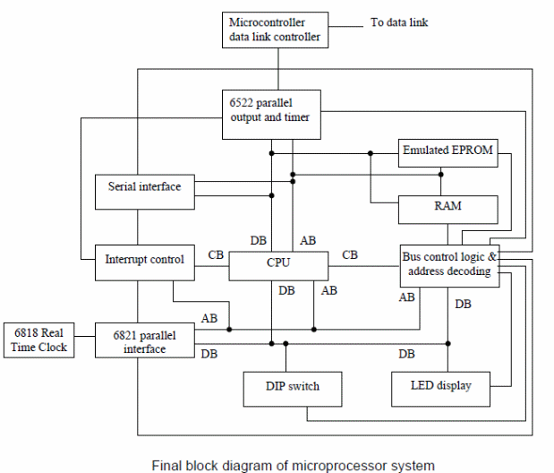
Additional Inputs and Outputs
To communicate with the pet feeding appliance and other components in the home we need to provide extra lines on 6821.
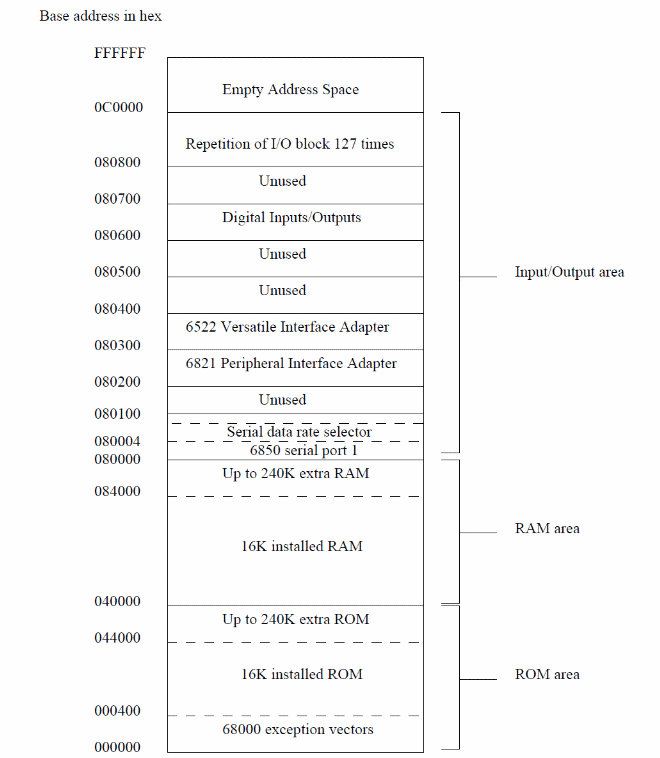
Address Decoding
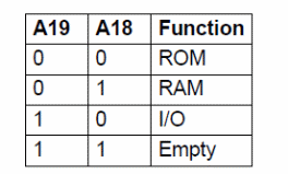
For the appropriate signals to be generated, a circuit called the address decoding circuit needs to be present to convert the memory map into a logic code that will agree with the address bus.
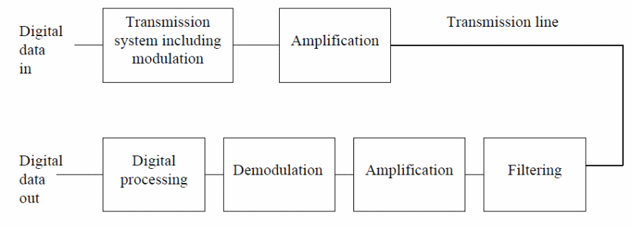
Finally, the signal is channeled to the individual appliances via the data link system. The system acts as the connector between the automated system and the specific appliances. Various methods can act as data link channels such as radiofrequency, infrared, and via the mains wiring. Of all these methods, the main wiring is the most appropriate since most if not all of the appliances will be connected to the mains hence eliminating the need for multiple connections.
Bus width: 8-bit versus 16-bit versus 32-bit processors
PIC 8-bit Microcontroller family
8-bit microprocessors offer supple memory options that may reach up to 128KB. The basic functioning system for an 8-bit microprocessor consists of 6-40 pins, 3KB program memory, a maximum of 144 bytes of RAM, a 2-level hardware stack, and an 8-bit file select register (Microchip Technology Inc. 2011, par.1).
8-bit microprocessors have several advantages when compared to 16-bit and 32-bit microprocessors. They offer a little set of learning instructions, have options of choosing speed since they incorporate an inbuilt oscillator system and encompass the reduced instruction set computing (RISC) architecture. Furthermore, they support an extensive portfolio of interfaces such as I2C, SPI, USB, USART, A/D, PWM, and Ethernet and they are relatively cheap.
68000 microprocessor family
This family of microprocessors was introduced in the late ’70s through the MACSS project. The basic functioning system consists of a 23-bit external address bus, an 8-bit microprocessor that can be extended to up to 2 MHz and has 64 KB RAM. This family has several advantages since it allows for flexibility in programming and can be expanded with ease to incorporate higher bits such as the 32-bit data and address buses for extra applications (Wikipedia 2011, par.5).
ARM Processor family
This family is an a32-bit processor that has found wide use in the technology industry. The basic ARM architecture is referred to as the Cortex-A series. ARM processors are preferred due to their high power efficiency and relatively lower cost when compared to other microprocessors. Furthermore, they are flexible and offer wide compatibility options with a myriad of platforms encompassing low power consumption capabilities (ARM 2011, par.4)
Applications of Microprocessors
PIC microcontrollers have found use in a series of wide-ranging applications that range from simple control logic applications to sophisticated Integrated Circuit systems. These Integrated Circuit systems make use of modes such as Universal Service bus (USB), ethernet, and LCD. Furthermore, they have found use in automotive lighting, motor control applications, and stand-alone companion chips. Despite these merits, the PIC family has confines that limit its application.
The initial designs had only a single accumulator and the whole RAM in the various devices could only be accessed through register-bank switching. Furthermore, the registers and operations were not orthogonal. The later versions such as the PIC 18 do not have an addressable hardware stack hence a prior task-switching procedure needs to be undertaken.
ARM microprocessors are widely used in many applications ranging from smartphones, smartbooks, netbooks, e-book readers, digital television, and many more platforms that require dynamic microprocessors. In the present world, phones, especially smartphones are part of peoples’ lives. These small yet powerful devices allow users to utilize an extensive list of applications at record speeds thanks to the ARM microprocessors.
Nowadays the state of the art smartphones such as the Nokia 900 has ARM microprocessor such as the Cortex-A8 and Cortex-A9 processors. Furthermore, the ARM platform consists of highly sophisticated engine systems that support user-friendly gaming and video editing experience on their mobile phones. This entails the use of the multicore processors such as the Cortex-A9. Furthermore, ARM has linked with a series of partners that provide ARM application-compatible platforms to allow for seamless and numerous applicability.
Examples of applications of ARM microprocessors include the use of ARM Cortex-A5, Cortex-A8, or Cortex-A9 processors in support of internet platforms on smartphones and netbooks. Touchscreen and haptic sensing mechanisms are under the control of the smallest microprocessors. The microprocessor used for such fine applications is the ARM’s Cortex-M0 processor.
ARM microprocessors have become popular as a result of their low cost when compared to other microprocessor families. In addition, these types of microprocessors are powerful in their size as they support a variety of simultaneous functions at very high speeds. Furthermore, they are energy efficient since they utilize less power.
This is demonstrated in smartphones where the battery lasts long despite the numerous applications and functions being undertaken by the chip. ARM microprocessors are versatile and as a result of this, they support a wide variety of peripherals ranging from USB to sophisticated systems employing haptic technology that supports real-time applications with out-of-this-world performance.
Circuit Map
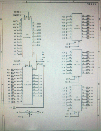
Connection of the ROM and RAM through the decoder is shown below in the memory map
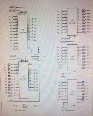
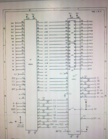
Decoding of the address bus from the memory chip is enabled by AS. The binary selects for the decoder will be served by address buses 17, 18, and 19. The ROM chips will be enabled by the YO and Y1 decoder lines while RAM will be enabled by lines Y2 and Y4 lines. Furthermore, the 68000 microprocessor address lines A1 to A16 will be mapped to the address lines A0 to A15 of the ROM and RAM chips. The data lines D0 to D15 will be mapped on the same lines of the ROM and RAM chips. The R/W will be connected to the WE on the RAM chip.
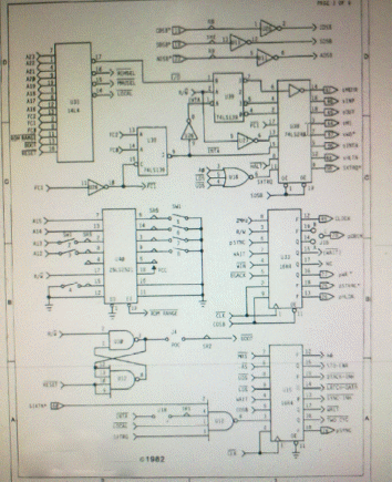
The system will employ a Universal Asynchronous Receiver/Transmitter (UART). It will be enabled from the Y5 output on the decoder chip. Address Lines A1 to A3 and data lines D0-D7 will be matched to corresponding buses on the UART. A master reset will then be performed. Since the UART has a slow operation, boosting is done by DTACK.
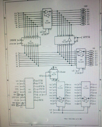
The installed timer chip will be connected to the microprocessor via its RS1 and RS0 to the A1 and A2 address lines of the 68000. In addition, data lines D8 to D15 will be connected to the PIAs D0-D7. For this system, a clock speed of 10 MHz will be used.
List of References
ARM 2011, Processors. Web.
Huang, H 2005, PIC microcontroller: An introduction to software and hardware interfacing, Cengage Learning, Stamford.
Microchip Technology Inc., 2011, 8-bit PIC® Microcontrollers. Web.
Wikipedia 2011, Motorola 68000. Web.