Introduction
A small local company manufacturing specialized machined ‘valve-body’ components for the petroleum industry wants to automate one of their existing manufacturing facilities. This proposed update is required in order maximize the profit margins of this particular facility by reducing operating costs and increasing overall operating efficiency. A Zilog Z80 microprocessor control system will drive this automated facility, which in turn acts as a slave controller to be controlled by a master PLC. The master PLC will give two digital outputs, the START bit and the STOP bit, which will control the slave controller (Microsoft 2001).
The Z80 microprocessor is chosen to run this system because of its simplicity to program over other processors. It also offers a good interrupt system that enables it to work efficiently. Another advantage is that it requires less hardware for clock generation, interfacing with the memory and also for power supply. Furthermore, it contains an advanced instruction set. This component, which includes bit manipulation and byte search instruction, is a very useful feature especially for the programmers coding for this processor. It also contains different registers that are helpful for programmers as well (Microsoft 2001).
Actuators are devices that are used to introduce movement to mechanical systems. Most often the time they achieve this by converting electrical energy into some form of mechanical movement (Hugh 1992). This installation requires the use of linear pneumatic actuators. A linear actuator is one which creates linear motion even if the force driving it is non-linear. This is very useful in cases where linear motion is required but the source of the motion is non-linear, such as an electric motor that produces circular motion. It is also specified that the actuators to be used be pneumatic ones. These types of actuators resemble cylinders with a piston inserted into them. Compressed air is used to alternatively pressurize the two sides of the piston. This causes the piston to move in a controlled line. The component connected to the piston also moves in the same way. The advantages of using these actuators to attain the linear movement required is that they are simple to use and install, yet they are also strong and do not wear out quickly. They happen to be very light and are also fast, which significantly affects the facility’s production for the better.
The owners of the manufacturing company want this facility to be divided into cells. Each cell will consist of two double acting linear pneumatic actuators and one double acting linear hydraulic actuator in order to process the proposed components. This will be the most cost effective arrangement for the facility and will ensure maximum productivity (Ciarcia 1981).
System Design
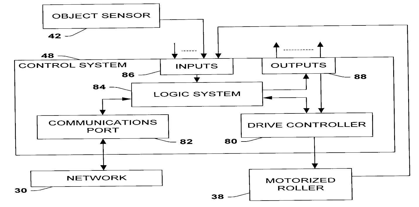
The system is designed such that the master PLC will control the Z80 microprocessor running the facility. Through it the person running the plant will be able to send a command to the microprocessor which will in turn start or stop the system. He will be able to give the input to the system through a keyboard. The input will then be processed by the processor, producing output that is then forwarded to the system for execution (Microsoft 2001). A schematic drawing of the input and output control structure is shown below.
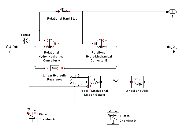
The cell will also consist of a number of conveyor belts through which the products being manufactured will be passing (Dillon 2011). This conveyor belt will be driven by the two double acting linear pneumatic actuators and one double acting linear hydraulic actuator. The schematics for this system are shown below.
Operation
The engineer running the plant will be responsible for the system’s operation (Hugh 1992). Through a keyboard he/she will type in the start command for the system. This command will be processed by the microprocessor which will produce the relevant binary instructions which will then be fed into the drive controller. This controller then takes over the system, executing the instructions as they are received from the microprocessor. The controller feeds instructions to the various parts of the system, causing the conveyor belts to start moving and the manufacturing process to begin. To stop the system the same process is repeated. The engineer inputs the stop instructions at the I/O module. The instructions are processed by the microprocessor and forwarded to the drive controller as binary instructions. The drive controller gives a kill signal to the cell components, thus stopping the conveyor belts and the entire manufacturing process. Due to the Z80’s processing power, the time taken from the point the engineer inputs instructions to the time the system responds is negligible, thus the efficiency of the system is maximized.
Memory mapping
A memory map is a data structure that lies in the memory itself and outlays how memory is laid out. Memory mapped I/O (MMIO) and ports I/O (PIO) are the two different ways of communication between the peripheral devices and the processor in a computer. This design incorporates PIO in the system, which uses a special class of CPU instructions specifically for performing input and output functions. With this system, the I/O devices have a separate address space from the main memory, and this is an advantage because sharing memory slows down the system (Wikipedia 2011). Below is a memory map for the manufacturing system.
Flowcharts
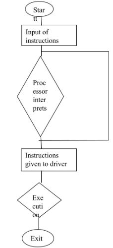
Flowcharts are essential tools that help in system design. They enable the people working on the project see how the different components of a system relate to each other in order to complete the task required. One concerned with this system is shown below. It shows how each component connects to the next and the communication that goes on in the system during execution of the instructions given to the system by the engineer (Samuelson 1984). From the flowchart, it is determined that execution is sequential and one part of the code must be executed before the next can be worked on.
Flow chart for running the program
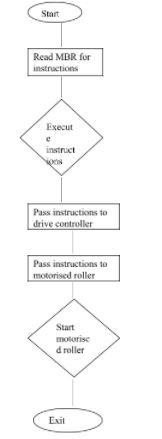
Flowchart for actuator cycle
Start process
Stop Process
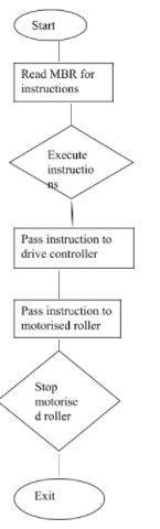
In the flowchart shown above, the process starts when the engineer inputs the instructions at the terminal. The microprocessor takes this input and processes it into code that the driver can understand. If the commands are wrong and the microprocessor is unable to comprehend them, then the process is taken back to the beginning for the engineer to input the instructions correctly. With the correct commands, the microprocessor successfully translates the input into machine language and passes it on to the driver. The driver then executes code, causing the actuators to start moving and the manufacturing to start. The process to stop the plant is technically the same, the only thing that will change are the instructions that the engineer will feed into the system.
Machine code program
Machine code program refers to the instructions that the processor passes on to the driver. This code is in a format that only the machine can understand but not a human. The engineer may give the system instructions in human readable code, but only after the code is translated into machine code can the system execute the code and achieve its directive (Samuelson 1984). The advantages of using machine code programming are that the programmer gets direct access to the hardware. This is advantageous because it makes the program faster since there is no time wasted in execution. It also contains numerous inbuilt tools availed to the programmer to help him get better control of the system (Ciarcia 1981). Its disadvantage is obvious, the reduced readability means that it is really hard to track down and correct errors in the code when they do occur. It also means that the code must be a hundred percent accurate, with absolutely no mistakes or an omission as there is no room for error. One small and seemingly insignificant error may result in the entire production line not working, thus slowing down or even completely stopping the production process. Below is an example of code that is written in machine language. The first part of the code readies the processor for accepting jobs.
- 0 DMA Control Enable
- 1 Parity Type (0=Odd, 1=Even)
- 2 Parity Enable (0=Off, 1=On)
- 3-4 Stop Bits (0=Sync Mode, 1..3 = 1bit, 1.5bit, 2bit)
- 5-6 Character Size (0..3 = 8bit, 7bit, 6bit, 5bit)
- 7 Prescaler (0..1 = /1, /16)
The next part of the code ensures the channels the processor will use to send instructions to the driver are open.
- 0 Transmitter Enable
- 1-2 Serial Output State (0=Hi-Z, 1=Low, 2=High, 3=Loopback)
- 3 Break
- 4 End of Transmission
- 5 Auto Turnaround
- 6 Underrun Error
- 7 Buffer Empty
The next part of the code ensures the driver is listening.
- 0 Receiver Enable
- 1 Sync Strip Enable
- 2 Match/Character in progress
- 3 Found/Search on Break Detect
- 4 Frame Error
- 5 Parity Error
- 6 Overrun Error
- 7 Buffer Full
The codes above prepare the system for receiving, relaying and transmitting of instructions.
Conclusion
In conclusion, the automation of the company’s manufacturing facility will be the right step in maximizing production, which will enhance the company’s profits. Splitting the manufacturing facility into cells is also advantageous since it enables different products to be produced in the same facility. The use of the Zilog 80 processor is another good move as this microprocessor has numerous advantages that ensure the system is fast. It is easy to program, which will make setting up the installation to be easy. It also has a lot of technical support especially on the internet, so it will be easy on the programmer and will also ensure the end result is more than satisfactory (Samuelson 1984).
The choice to use linear pneumatic actuators was also good. They are lightweight, their installation and usage is easy (Dillon 2011). They also do not wear out quickly and are very fast, which leaves the positive impact of improving production speed within the facility which is one way for the company to maximize production. The organization has also opted to go with top-down design methodology, which will be beneficial as it helps them to visualize the entire project and also divide it into phases that will enable faster and thorough completion of the project (Dillon 2011). The use of machine language is however debatable since its disadvantages in my opinion far outweighs its advantages. One small error may cause the entire plant to stop, and due to the language’s difficult readability, it will be very hard for the programmer to track down the particular error and fix it quickly. It is however my opinion that the automation of this facility is feasible and will result in better results for the company, both in the quality and quantity of goods produced by the facility as well as reduce the cost of production, hence maximizing profits.
References
Ciarcia, S., 1981. Build Your own Z80 Computer: Design Guidelines and Application Notes. Sydney: Elsevier.
Dillon, M., 2011. What Do Memory-Mapped Files Have to Offer? Web.
Hugh, P., 1992. Solenoids. Web.
Microsoft, 2001. Partial Address Decoding and I/O Space in Windows Operating Systems. Sydney: Elsevier.
Samuelson, P., 1984. CONTU Revisited: The Case against Copyright Protection for Computer Programs in Machine-Readable Form. Duke Law Journal, 1(4), pp.663-769.